Revolutionizing Technology with Ultrafast Fiber Lasers

In the fast-paced world of technology, innovation is the key to progress. From communication systems to manufacturing processes, the need for speed, precision, and efficiency is ever-present. One remarkable technology that has been making waves in various industries is the Ultrafast Fiber Laser. This cutting-edge technology is transforming the landscape of applications that require high-intensity, ultrafast laser pulses. In this blog, we will delve into the world of Ultrafast Fiber Lasers, their applications, and their potential to reshape our future.

What are Ultrafast Fiber Lasers?

Ultrafast Fiber Lasers are a type of laser system known for their remarkable capabilities. These lasers generate extremely short laser pulses, typically on the order of femtoseconds or picoseconds. This ultrafast pulse duration is a fundamental feature that sets them apart from traditional laser systems. Fiber lasers use optical fibers as the gain medium, allowing for a compact and robust design.

Applications in Medicine

The medical field has witnessed significant advancements due to Ultrafast Fiber Lasers. Their precise and controlled energy delivery is indispensable for laser surgery, eye surgery, and dermatological treatments. These lasers can selectively target tissues, minimizing damage to surrounding areas. This precision is particularly beneficial in delicate procedures, such as eye surgeries, where the safety of the patient is of utmost importance.

Materials Processing and Manufacturing

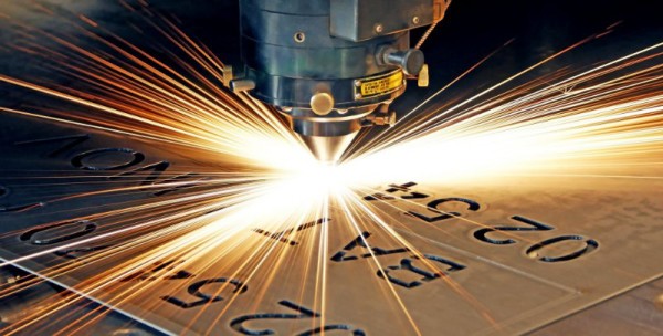
Ultrafast Fiber Lasers have also found their niche in materials processing and manufacturing. They are instrumental in the world of micromachining, a process that involves creating intricate and minuscule structures in materials like metals, semiconductors, and ceramics. The ultrafast pulses allow for high-precision cutting and drilling, enabling the production of intricate components for various industries, including aerospace and electronics.

Scientific Research

In the realm of scientific research, Ultrafast Fiber Lasers have become invaluable tools. They are used in a wide range of applications, from ultrafast spectroscopy to studying chemical reactions at the molecular level. Researchers can observe and analyze processes that occur in a fraction of a second, shedding light on previously uncharted territories of science.

Telecommunications

Ultrafast Fiber Lasers play a crucial role in the telecommunications industry, facilitating the transmission of vast amounts of data at incredible speeds. Their ability to generate ultra-short pulses enables the efficient transmission of information through optical fibers, making high-speed internet and telecommunications networks a reality.

Environmental Sensing

Environmental monitoring and sensing benefit from the precision and sensitivity of Ultrafast Fiber Lasers. They are used in LIDAR (Light Detection and Ranging) systems, which provide highly accurate distance and speed measurements. These systems are used in applications ranging from autonomous vehicles to atmospheric research.

The Future of Ultrafast Fiber Lasers

As technology continues to advance, the applications of Ultrafast Fiber Lasers will only expand. Their compact design and exceptional performance make them an attractive choice for a wide range of industries. Whether it’s in medical procedures, materials processing, scientific research, telecommunications, or environmental sensing, these lasers have the potential to revolutionize the way we approach various tasks.

In conclusion, Ultrafast Fiber Lasers are a remarkable innovation that is already leaving a significant mark on several industries. Their precision and speed are changing the way we perform medical procedures, manufacture products, conduct scientific research, and communicate. As the technology continues to evolve, it’s safe to say that we’ve only scratched the surface of what Ultrafast Fiber Lasers can achieve. The future looks bright, and it’s powered by light – ultrafast light, to be precise.

Important Things to Know About Fiber Lasers

Fiber Bragg Gratings for fiber laser

Fiber lasers are ubiquitous in today’s environment. They are frequently used in industrial settings to carry out cutting, marking, welding, cleaning, texturing, drilling, and much more due to the various wavelengths they can produce. They are also employed in other industries, like telecommunications and medical.

Fiber lasers transmit light along an optical fiber cable consisting of silica glass. Due to its straighter and smaller shape compared to other types of lasers, the resulting laser beam is more precise. Additionally, they feature a compact design, outstanding electrical efficiency, require little maintenance, and have cheap operating expenses.

What Are the Different Types of Fiber Lasers?

In general, the following attributes can be used to classify fiber lasers:

  • Laser Source:

The substance that the laser source is combined with determines the characteristics of a fiber laser. Due to the fact that each of these laser types produces a different wavelength, they are all used for various applications.

  • Mode of Operation:

Different laser designs emit laser beams in various ways. When using “q-switched,” “gain-switched,” or “mode-locked” lasers, high-peak powers can be achieved by pulsing laser beams at a predetermined repetition rate. Alternatively, they might convey the same amount of energy continuously if they were continuous (continuous-wave fiber lasers).

  • Laser Power

The average power of the laser beam is measured in watts or laser power. Compared to low-power lasers, high-power lasers produce more energy more quickly.

  • Mode:

The model describes the size of the optical fiber’s core, which is where light travels. Single-mode fiber lasers and multi-mode fiber lasers are the two different kinds of modes. Single-mode lasers typically transmit laser light more effectively and produce superior beams.

The Benefits of Fiber Lasers

Fiber lasers have advanced significantly and now offer a number of intriguing advantages as a result of the diligent effort of numerous academic and commercial researchers and engineers.

Convenience:

In general, fiber lasers are more compact than conventional lasers of comparable power, and the fact that the laser is housed in a flexible fiber makes beam distribution easier.

  • High power:

Having the gain medium dispersed across a wide area has two implications. First of all, you can get a lot of amplification, and secondly, since there is so much usable surface, dispersing heat is not a problem.

  • Consistent beam quality:

When heat and vibration are present in the environment, fiber lasers still create and deliver high-quality beams.

What Is the Lifespan of a Fiber Laser?

According to many online sources, CO2 lasers only last 30,000 hours while fiber lasers last 100,000 hours. These figures pertain to a quantity known as “mean time between failures” (MTBF), which varies depending on the specific fiber laser in question. For various fiber laser types, you will actually see different numbers.

The MTBF calculates a laser’s dependability by stating the anticipated number of hours of operation before a failure. It is calculated by testing several laser units, adding up the results, and dividing the result by the total number of failures.

This value gives you a good indication of the fiber laser’s dependability even though it cannot precisely tell you how long it can operate.

How Do Fiber Lasers Operate?

Pump light for fiber lasers comes from so-called laser diodes. The light that is sent into the fiber-optic cable is emitted by these diodes. The subsequent step involves creating and amplifying a certain wavelength using optical components. The final step is to shape and release the generated laser beam.

Step 1: The Laser Diodes Produce Light

Step 2: The Fiber-Optic Cable Guides the Pump Light

Step 3: The Laser Cavity Amplifies Light

Step 4: Produce Laser Light with a Specific Wavelength

Step 5: Shape and Release of the Laser Beam

DKphotonic offers a comprehensive range of laser power measurement solutions for various laser types, including fiber lasers.

Multimode pump combiners now accessible from the place of dk photonics!

Pump combiner is a passive segment, fabricated in view of fused biconical taper (FBT) strategy, generally utilized as a part of fiber laser, fiber amplifier, high power EDFA, biomedical and sensor systems, and so on. DK photonics offers pump combiners worked by engineers with strong information and specialized foundation; they remain by high caliber and financially savvy items with our awesome administrations too.

(2+1)x1 Pump and Signal Combiner

Sorts of Multimode Pump Combiners

2x1pump combiner

DK photonics’ 2×1 multimode pump combiner is intended for high power applications. It highlights excellent optical qualities. These gadgets can be utilized to join the power from a few multimode laser diodes, conveying the consolidated power for applications in modern, military, therapeutic and broadcast communications markets. It has a heat sink package and a hole for temperature monitoring. DK photonics’ multimode combiners offer efficient power exchange for high power applications like direct diode materials handling and pump cascading with a maximum conservation of brightness.

4×1 pump combiner

It highlights extraordinary optical characteristics. These gadgets can be utilized to consolidate the power from a few multimode laser diodes, conveying the joined power for applications in modern, military, restorative and broadcast communications markets. It has a warmth sink bundle and a gap for temperature observing.

19×1 pump combiner

DK photonics’ 19×1 multimode pump combiner is intended for high power applications. It highlights outstanding optical qualities. These gadgets can be utilized to consolidate the power from a few multimode laser diodes, conveying the joined power for applications in mechanical, military, medicinal and broadcast communications markets. It has a warmth sink bundle and a gap for temperature checking. DK photonics’ multimode combiners offer effective power exchange for high power applications like direct diode materials handling and pump falling with a greatest preservation of splendor.

3×1 pump combiner

DK photonics’ 3×1 multimode pump combiner is intended for high power applications. It highlights remarkable optical attributes. These gadgets can be utilized to join the power from a few multimode laser diodes, conveying the consolidated power for applications in modern, military, medicinal and media communications markets. It has a warmth sink bundle and a gap for temperature observing.

7×1 pump combiner

DK photonics’ 7×1 multimode pump combiner is intended for high power applications. It highlights outstanding optical qualities. These gadgets can be utilized to consolidate the power from a few multimode laser diodes, conveying the joined power for applications in mechanical, military, medicinal and media communications markets. It has a warmth sink bundle and an opening for temperature observing.

DK photonics offers pump combiners worked by engineers with strong learning and specialized foundation; offer high caliber and financially savvy items with our incredible administrations also.

Learning the Different Coating Stripping Methods

The cladding power stripper also referred to as the multimode optical power stripper is designed for amplifier applications and high power fiber laser. It is an ideal device  for ASE, residual pump power stripping, core modes that have escaped from double cladding fibers inner cladding while ensuring preservation of single power minimal degradation and beam quality (M2). Single power that is reflected into the inner cladding may also be stripped out too.  The handling capability of the stripping power goes to 800W or at times may be even higher

Stripping the Coating

The fibers that most reputable companies supply all come with a standard  acrylate single layer coating or, in some such as the high power products, a coating that is high temperature enduring. In comparison to dual layer coatings, the coatings that are single layer are more brittle and smooth. The coating can be removed readily using the conventional tools for fiber stripping such as the Fitel S-210 Clauss or CFS-1 for 125 μm cladding diameter fiber or for larger cladding diameters the Clauss No Nik stripper is used. For fibers whose outer diameter is non-standard, it is recommended that an adjustable stripper is used.  Thermal strippers such as those that are attached to the Schleuniger FiberStrip 7030 or the Vytran FFS-2000 can be used for all fiber in a safe way.

Alternatively, chemical stripping of fibers can be done using an appropriate solvent. For example, the coating can be exposed for one minute to sulfuric acid at 120°C sulfuric acid. Before the fiber is dipped into the liquid, the tip should be sealed with a drop of glue of 2 mm in diameter or through the end fiber hole collapsing using a fusion splicer.  It is worth noting that most glue types are dissolved in this acid, but epoxies that are two-component such as the Epotek ND353 tends to dissolve in a slower manner than the coating.

It is also possible to obtain chemical stripping through application on the fiber tip, of paint stripper. The paint stripper is usually in the form of a gel so as to reduce the occurrence of out-gassing and can be applied easily using a small brush. After a minute or so, the coating becomes soft and is removed easily using a lens tissue. It is worth noting that paint stripper typically contains dichloromethane (CH2Cl2) and as such there may be restrictions by local regulations to use it. For lower quality and faster stripping, another option would be to use a normal cigarette lighter to burn the coating off. However, the fiber may end up becoming brittle hence not the best choice for stripping.

DK Photonics now can write Fiber Bragg Gratings for fiber lasers on demand

Fiber Bragg Gratings for fiber laser
Laser Mirror Gratings

China, 21th July, 2016: Optical passive components available at DK Photonics are significant in a number of industries such as telecommunication applications, fiber laser, etc. In order to better give our fiber laser customers to do matching service, DK Photonics work with a Chinese optical research institute, after more than half a year’s efforts, and finally produced the FBG Mirrors used for fiber laser.

FBG Mirrors are based on the reflective properties of the Fiber Bragg Grating (FBG) written in the core of an optical fiber waveguide. FBG mirrors’ principal application is to use a high and low reflector to form a stable laser cavity having the lasing wavelength selected by the low reflector.

Fiber Bragg grating (FBG) is a distributed reflector constructed in an optical fiber short segment that allows reflecting particular wavelengths and transmitting the rest of them. The periodic variation of the fiber core refractive index generates a wavelength-specific dielectric mirror, which allows reflecting specific wavelengths. FBG can be used as a high reflector (HR) and output coupler (OC) to make a laser cavity in a fiber laser. Rare earth doped optical fiber increases the laser gain. The major advantage of all-fiber systems where free space mirrors are replaced with a pair of fiber Bragg gratings (FBG’s) is that the realignment process is no longer needed for the entire system functioning period, since FBG is spliced directly to the doped finer and never needs adjusting.

DK Photonics can provide varied wavelengths FBG, such as 1018nm, 1053nm, 1064nm, 1080nm, 1550nm, 1950nm, 2020nm, 2040nm; and can write in all common passive optical fibers, such as 6/125DCF,10/125DCF,15/130DCF,20/125DCF,25/250DCF,30/250DCF,20/400DC Fiber, PM or non-PM types are available. The Max. handling power up to 1000W. The following is main parameter or our FBG:

Parameters Values
Center Wavelength(nm) 1018nm, 1053nm, 1064nm, 1080nm, 1550nm, 1950nm, 2020nm, 2040nm
Wavelength accuracy 0.2nm
High Re­ector / Output Coupler HR OC
Reflectivity ≥99% 3%~20%
Bandwidth 1~3nm 0.2~1nm
Fiber Type 10/125 DCF,15/130DCF, 20/125 DCF,25/250 DCF,30/250 DCF,20/400 DC Fiber, PM or non-PM types are available
Power Handling(core) 20W, 50W, 100W, 500W,1000W.

Applications

FBGs offer multiple applications. It can replace conventional dielectric mirrors to provide optical feedback. It can be also used to create a multi-wavelength Raman fiber laser.

Fiber lasers offer a compact, electrically efficient alternative to Ar-Kr and Nd:YAG technologies. The FBG can be applied to fiber lasers of any type:

  • Single frequency fiber lasers;
  • Raman fiber laser;
  • Fixed frequency visible wavelength lasers;
  • Tunable frequency visible wavelength lasers;
  • Ytterbium doped fiber lasers;
  • Q-switched fiber lasers;
  • Pulsed fiber lasers;
  • Stabilized multi-mode emission sources;
  • Fine optical fiber responder, etc.

To obtain more information about the products, visit http://www.dkphotonics.com/.

About DK Photonics

The DK Photonics claims that they even provide customized solutions to their patrons. Those industries who wish their products to be distinctive can contact them for the same. The team mentions that they have passed the ISO9001 quality tests and hence, there is no compromise in this aspect.

Pump and signal combiner for bi-directional pumping of all-fiber lasers and amplifiers(10)

7. Signal feedthrough of the fiber combiner

Besides the pump power handling and the pump coupling efficiency of a fiber combiner, it is important for fiber laser and amplifier applications to maintain the optical properties of the signal light propagating through the fiber combiner. In particular, during the fabrication of the fiber component, externally induced mechanical stress and perhaps a marginal fraction of thermal diffusion of the core dopants [19] can result in a high signal insertion loss in conjunction with a degradation of the signal beam quality. This behavior was expected for large mode area DC fibers with a very low core refractive index (NA ~0.06), and therefore possible beam quality degradations of the signal feedthrough light was investigated (in Section 7.1).

The uninterrupted signal core in the fiber combiner provides the possibility of passing a signal beam through the combiner in forward and backward direction. However, in the case of a backward propagating signal, the pump diodes need sufficient protection against the signal. Thus, in Section 7.2 we investigate the signal to pump isolation of a 4 + 1×1 fiber combiner in a fiber amplifier setup.

7.1 Signal insertion loss and beam quality

In order to determine possible beam quality degradation and a signal insertion loss caused by the signal feedthrough of the combiner, the setup depicted in Fig. 14

fiber combiner

Fig. 14 Setup for beam quality measurements, TF: target fiber, PBS: polarization beam splitter.was used. A signal at a wavelength of 1064 nm was launched into the core of a 2.75 m long Ytterbium-doped DC fiber (Nufern YDF-25/250), which is specified with a signal core diameter of 25 µm (NA 0.06) and a pump core diameter of 250 µm (NA 0.46). Thus, the parameters of the passive TF of the combiner were matched to the active fiber. The coiling diameter of the active fiber was 12 cm to maintain near diffraction limited beam quality [20]. The transmitted signal had a power of about 200 mW and was propagating in reverse direction through the fiber combiner. The beam quality measurements were carried out with a Fabry-Perot ring-cavity. With this cavity it was possible to determine the power fraction in higher-order transversal cavity modes with respect to the Gaussian TEM00 mode by scanning the length of the ring-cavity over a free spectral range (FSR). A detailed description of the measuring setup can be found in Ref [21]. Due to the use of a polarization sensitive beam quality measurement, a half- and a quarter-wave retardation plate in conjunction with a polarization beam splitter (PBS) were used. The determined polarization extinction ratio was better than 17 dB after the propagation of the signal through the active fiber and the fiber combiner.

Before the fusion splice between the active fiber and the 4 + 1×1 combiner, the power in higher-order modes of the active fiber was determined. This measurement served as a reference beam quality for the active fiber. The mode scan in Fig. 15(a)

fiber combiner 2

Fig. 15 Normalized transmitted intensity through a premode cleaner as a function of the ring-cavity length in units of a free spectral range for (a) the reference beam and (b) the signal feedthrough beam of a 4 + 1×1 fiber combiner.

shows the logarithmic normalized intensity over a free spectral range for the reference beam with a power in higher-order modes of 3.1%. This results in a fundamental fiber mode power of at least 96.9% for the reference beam. For the signal feedthrough of the fiber combiner, a power in higher-order modes of only 5.1% was found (Fig. 15(b)).

Consequently, the signal feedthrough fiber (0.7 m long TF) only led to an increase in power in higher-order transversal modes of maximal 2%. Furthermore, it must be considered that additional power transfer to higher-order transversal modes can also be caused by the fusion splice between the active DC fiber and the TF. Hence, good preservation of the signal beam quality, in conjunction with the low signal insertion loss of less than 3%, provides an excellent high power fiber component for monolithic fiber laser and amplifier systems.

Work Theory of the Laser Cutting Machine(2)

Cutting methods of laser cutting machine

Vaporization cutting

It means that vaporization is the main way to remove the processed material. In the process of vaporization cutting, workpiece surface is heated to vaporization temperature quickly by focused laser beams, forming High pressure steam and spraying outward at supersonic speeds. In the meantime, a hole is formed in the laser active area and laser beams reflex several times in the hole to increase the absorption of laser pump power combiner by material.

When high-pressure vapors spray outward, the melted materials are blown away in the kerf till the workpiece is finally cut. Vaporization cutting needs very high power density, which is eighth power of ten watt above per square centimeter. It is usually applied in low flash point materials and refractory materials.

Reaction Fusion Cutting

Reaction Fusion Cutting

When assistant airflow not only blows the melted materials from the kerf but also has thermal reaction with the workpiece, this is the so-called reaction fusion cutting. Gases that can have reaction with workpiece are oxygen or mixture gases containing oxygen. When the surface  temperature of workpiece reach to ignition temperature, strong combustion heat release occurs to improve the laser cutting ability.

Combustion heat release of low carbon steel and stainless steel is 60%. And it is about 90% for reactive metals like titanium.

Compared to vaporization cutting and general fusion cutting, reaction fusion cutting need less laser power density. However, reaction fusion cutting may effect the performance of worpiece since the combustion reaction can lead to chemical reaction on materials.

Fusion Cutting

When adding a assistant airflow system coaxial with laser to  blow the melted materials away from kerf, this kind of cutting is fusion cutting. In fusion fiber coupler cutting, workpiece needn’t to be heated to vaporization temperature so the required laser power density is reduced greatly.

Laser Scribing

It is mainly used in semiconductor materials, in which laser of high power density make a shallow groove in the semiconductor materials of the workpiece and then makes it crack through mechanistic or vibratory methods. The quality is valued by the surface fragments and size of heat affect area.

Cold Chipping

It is a new processing method, which is put forward along with ultraviolet band superpower excimer laser appeared in recent years. The basic theory is that energy of ultraviolet photons is similar to binding energy of many organic materials; this high-energy photons are used to impact bond organic materials thus make it crack, achieving purpose of cutting. This new technology has promising application future, especially in electron industry.

Thermal Stress Cutting

Mechanism of thermal stress cutting is that laser beams heat an area of fragile material to produce evident temperature gradient. The high surface temperature makes expansion and inner lower temperature hinders expansion, forming pulling stress in the surface and radial crushing stress inside. When the two stresses exceed fracture limit strength of the workpiece, crackle appears. And then the workpiece is broken along the normal direction of the crack. It is suitable for glasses and ceramics.

Conclusion: laser cutting machine is a cutting technology of melting and gasifying surface material through focused energy generated by the use of laser specialties and focused lens. It features good cutting quality, high speed, various cutting material and high efficiency.

About DK Photonics

DK Photonics – www.dkphotonics.com  specializes in designing and manufacturing of high quality optical passive components mainly for fiber laser applications such as 1064nm high power isolator, Cladding Power Stripper, Multimode High Power Isolator, pump combiner,1064nm Band-pass Filter,(6+1)X1 Pump and Signal Combiner, PM Circulator, PM Isolator, optical Coupler. More information, please contact us.


Work Theory of the Laser Cutting Machine(1)

Laser has been applied in teaching, military as well as industrial production. Laser cutting machine is one of the applications. It can be used in both metal and non-metal cutting, Melting surface material by laser beam. This article will discuss the work theory of laser cutting machine.

Introduction on the work theory of laser cutting machine

Introduction on the work theory of laser cutting machine.

Laser cutting machine adopts the energy released on the time when laser beam irradiate metal surface. The metal is melt by laser and sinter is blow away by gas. Because laser power is highly focused, only a very little heat effects the other part of metal plate and causes a little or no deformation. Laser can cut any complex shape precisely, which needs no further processing.

Laser source is generally CO2 laser beam high power isolator with operating power of 500~5000W. The power is even lower than that of many household electric heater, and because of lenses and reflectors, laser beams are focused in a very small bit of area. Highly focused energy heat the area quickly and makes the metal plate melted.

Laser cutting machine can cut stainless steal of thickness less than 16mm; when adding oxygen in laser beam, the cutting thickness is 8~10mm but it will generate a thin oxidation film in the cut surface. The maximum thickness is 16mm which leads to larger cutting deviation on the size of components.

Since the advent of laser, numerous laser products have been developed, such as laser printer, laser cosmetic instrument, laser marker, laser cutting machine etc. Due to its late start in China, the laser technology in China is greatly behind the developed countries. Although Chinese manufacturers can produce plenty of laser products, some key parts such as laser tube, driving motor, galvanometer and focus lens are imported products. This leads to an increase on cost thus an increase on consumer’s payment.

In recent years, domestic research and production of  laser products become closer to advanced overseas products with the progress of laser technology in China. Some aspects are even superior to products abroad, which has a leading role in market because of the  advantages of price. Overseas products have absolute predominance in precision machining for its quality on stability and endurance.

Work theory of laser cutting machine

Work theory of laser cutting machine

Laser tube is the core part of laser cutting machine. So, below is an introduction of the most popular laser tube. CO2 laser tube.

Laser tube is composed of hard glasses, so it is fragile. It adopts layer of sleeve construction with discharge tube in the most inside layer. However, the diameter of discharge tube is thicker than laser tube, diffraction between the thickness of discharge tube and the size of flare is in direct ratio; the length of tube is in proportion to output power of discharge tube.  Laser tube generates a large quantity of heat in the operation of laser cutting machine, which influences the normal work. So cold water machine is needed to cool laser tube, ensuring constant temperature for successful running.

Cutting features of laser cutting machine

Advantages of laser cutting:

One — high efficiency

Laser cutting machine is always connected to several numerically-controlled rotary tables to achieve numerical controlled cutting. It only needs to change the NC program to adjust to components of different shapes, which can make 2D cutting as well as 3D cutting.

Two — high speed

When cutting low carbon steel sheets of 2mm thickness, the speed of 1200W laser cutting is 600cmmin; when it is 5mm thick polypropylene resin plate, the cutting speed is 1200cmmin. The material needs no clamping fix in laser cutting process.

Three — high quality cutting

Laser cutting features thin kerf. The two sides of kerf are parallel and the kerf is vertical to the surface. The cutting precision can reach to ±0.05mm. The cutting surface is clean and nice, with roughness of tens of microns. The cut components can even come into use directly without further machining. After laser cutting, the heat effected area is very small and material near to kerf has not been affected, making little deformation, high cutting precicion and perfect geometrical shape

Four — non-contact cutting

Laser cutting is non-contact cutting, which means no tool wear problem. When processing different shapes, there is no need to change tools, the only way is to alter the output parameter of laser. The whole laser cutting process features low noise, little vibration and little pollution.

Five — various cutting material

Compared to oxyacetylene cutting and plasma cutting, laser cutting can be applied on more materials, including metal and non-metal, metal matrix and non-metallic matrix composite, leather, wood as well as fibers.

About DK Photonics

DK Photonics – www.dkphotonics.com  specializes in designing and manufacturing of high quality optical passive components mainly for fiber laser applications such as 1064nm high power isolator, Cladding Power Stripper, Multimode High Power Isolator, pump signal combiner,1064nm Band-pass Filter,(6+1)X1 Pump and Signal Combiner, PM Circulator, PM Isolator, optical Coupler. More information, please contact us.

Pump and signal combiner for bi-directional pumping of all-fiber lasers and amplifiers(9)

6. Demonstration of 440 W pump power handling

After detailed theoretical and experimental characterization of fiber pump combiners with multiple pump ports, a pump power handling performance test was conducted. For these investigations each pump port of a 4 + 1×1 combiner was connected to a fiber coupled pump diode (nLight Pearl) with an output power of ~110 W at a wavelength of 976 nm. The PFF and the delivery fiber of the pump diode had a core diameter of 105 µm with a NA of 0.22. At each fiber output end of the IF, a pump light stripper was applied to avoid the Fresnel reflection of the TP, and therefore the TP was not measured. Up to the maximum total pump diode power of 440 W, a coupling efficiency of 90.2% was experimentally determined (Fig. 13

fiber pump combiners

Fig. 13 Combined pump power for a 4+1×1 high power fiber combiner, * ratio of coupled power to total diode power in percent.

). In the simulations a slightly higher coupling efficiency of 92.8% was obtained. The difference of 2.6% in simulated and measured pump light coupling must be distributed among TP, PAA and PCT, with simulated values of 3.0, 1.4 and 1.7%, respectively. It can be assumed that the PAA-fraction is higher than 1.4%, since the fibers of the combiner are contaminated with dust particles in spite of intensive cleaning. If we assume for each individual loss mechanism an error of 1% related to the total diode power then PCT was 7.5 W ± 4.4 W, i.e. the coating of the TF and the pump power stripper had to handle this fraction of power.

About DK Photonics

DK Photonics – www.dkphotonics.com  specializes in designing and manufacturing of high qualityoptical passive components mainly for fiber laser applications such as 1064nm high power isolator,Cladding Power Stripper, High Power Isolator,pump combiner,1064nm Band-pass Filter,(6+1)X1 Pump and Signal Combiner,PM Circulator,PM Isolator,optical Coupler.More information,please contact us.

Pump and signal combiner for bi-directional pumping of all-fiber lasers and amplifiers(8)

Pump and signal combiner for bi-directional pumping of all-fiber lasers and amplifiers(8)

5.2 Simulations of the loss mechanism caused by additional pump ports

As already discussed, the total power loss is comprised of TP, PAA and PCT. Since a TL of 20 mm and a TR of 6 seem to be promising parameters for a fiber combiner with multiple pump ports, Fig. 9

pump combiner

Fig. 9 Simulated losses for a pump combiner with a TL of 20 mm and a TR of 6 providing up to 6 pump ports. Please see Fig. 1for TP, PCT and PAA.

illustrates the behavior of the 3 different loss mechanisms and the total power loss against the number of pump ports. The input pump light NA of the PFFs was 0.22. The simulations clearly show that the TP-fraction as well as the PAA-fraction increase with the total power loss, and the PCT-fraction stays almost constant. The NA-mismatched pump light, which couples into the coating of the target fiber (PCT) can be kept below 1.7%, even up to 6 pump ports. Hence, an increasing number of pump ports and, therefore, scaling of the combined pump power results in additional power losses, but with an insignificant increase of thermal load to the coating of the TF. Of course, due to an increased PAA the combiner housing would be exposed to a higher thermal load, but this can be handled by an adequate thermalconcept. The increased PAA can be explained by pump light rays which couple back from the TF into one of the IFs, further propagate in the converging taper portion of the IF, increase in NA and undergo refraction into the ambient air. The increase of the TP-fraction with additional pump ports can be caused by pump light rays with a low NA which reverse couple into one of the IFs and further propagate there.

Finally, the simulations show that the total pump power loss increases with each additional pump port but the PCT, resulting in thermal load of the TF, does not increase significantly compared to a fiber combiner with a single pump port. In general, for the optical design of a side-pumped coupler with multiple pump ports, a TL as short as possible in conjunction with a TR as low as possible, but still satisfying the required pump coupling efficiency for the desired number of pump ports, ensures efficient pump light combining with low power losses. In contrast, for a single pump port, a longer TL in conjunction with a low TR is advantageous for increasing the pump coupling efficiency and reducing PCT-losses in particular.

5.3 Experimental characterization of pump combiners with multiple pump ports

Since the simulation results indicate that a TL of 20 mm and a TR of 6 are useful taper parameters, fiber combiners with two, four and six pump ports were developed. Each pump port consisted of an IF with a measured TL of 18 mm and a measured TR of 6.7. Each PFF had a NA of 0.15, and to characterize the combiner was connected to a pump diode (Oclaro BMU25) with a pigtail fiber delivering a maximum output power of about 25 W at a wavelength of 976 nm. The delivery fiber of the pump diode had parameters identical to the PFF.

Figure 10(a)

2

Fig. 10 (a) Combined and transmitted power measured for a fiber combiner with 4 pump ports and (b) combined pump power measured for a fiber combiner with 6 pump ports, * ratio of coupled or transmitted power to total diode power in percent.

shows the total diode power with respect to the combined pump power and TP for a fiber combiner with four pump ports. For the combined pump power a coupling efficiency of 92% (93.1% in the simulation) was measured, and the fraction of TP was 3.6% (3.9% in the simulation) compared to the total diode power. Thus, the measured TP of 3.6% was 45% of the total power loss of 8% (Fig. 10(a)). Based on the good agreement between simulation and experiments it can be assumed that the PCT-fraction and PAA-fraction were about 0.6% and 2.3% of the total diode power, respectively.

Microscope images of the top view and of the cross section view, close to the taper waist, of a fiber combiner with 4 pump ports are depicted in Fig. 11(a)

3

Fig. 11 Microscope image of (a) the top view and (b) the cross section view of a fiber combiner with 4 pump ports.

and 11(b).

The experimental results of a developed six pump port fiber combiner with a combined pump power of 141.5 W and an obtained coupling efficiency of 89.6% (91.1% in the simulations) is shown in Fig. 10(b). The fiber combiner with six pump ports was limited by the available pump power and not by thermal problems. For the combiner presented in Fig. 10(b), Fig. 12(a)

4

Fig. 12 (a) Pump coupling efficiency of the individual pump ports of the six pump port fiber combiner presented in Fig. 10(b) and10(b) comparison of the experimentally achieved pump coupling efficiencies with the simulation results for fiber combiners with multiple pump ports.

shows the pump coupling efficiency of each individual pump port with a maximum and minimum pump coupling efficiency of 90.2 and 88.8%. The difference of only 1.4% indicates a very homogeneous fiber bundle structure, and supports the assumption of identical optical behavior of the individual pump ports.

An overview of the experimentally obtained coupling efficiencies with the corresponding simulation results for a fiber combiner with 1, 2, 4 and 6 pump ports is depicted in Fig. 12(b). An agreement of the experimental and simulated results within 1% confirms the applicability of the simulation approach for multiple pump ports. For each fiber combiner a TL of 18 mm, a TR of 6.7 and a PFF with a core NA of 0.15 was applied.

About DK Photonics

DK Photonics – www.dkphotonics.com  specializes in designing and manufacturing of high qualityoptical passive components mainly for fiber laser applications such as 1064nm high power isolator,Cladding Power Stripper,Multimode High Power Isolator,pump combiner,1064nm Band-pass Filter,(6+1)X1 Pump and Signal Combiner,PM Circulator,PM Isolator,optical Coupler.More information,please contact us.