CWDM Mux/Demux: Simplifying Fiber Optic Communication

Optical fiber communication has revolutionized the way data is transmitted over long distances, enabling high-speed internet, telecommunication, and more. Among the many components involved, CWDM Mux/Demux plays a crucial role in maximizing the efficiency of optical networks. Let’s delve into what CWDM Mux/Demux is and how it works:

What is CWDM Mux/Demux?

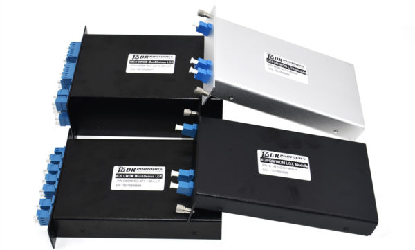
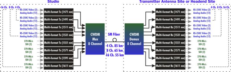
CWDM stands for Coarse Wavelength Division Multiplexing. CWDM Mux/Demux is a passive optical component used in fiber optic communication networks to combine multiple optical signals of different wavelengths onto a single fiber or to separate these signals back into individual wavelengths.

How Does CWDM Mux/Demux Work?

CWDM Mux/Demux operates based on the principle of wavelength division multiplexing (WDM). It consists of multiple input and output ports, each corresponding to a specific wavelength channel. The Mux (Multiplexer) combines several incoming optical signals with different wavelengths into a single fiber, while the Demux (Demultiplexer) separates these signals back into individual channels at the receiving end.

Benefits of CWDM Mux/Demux:

  • Increased Bandwidth: By utilizing different wavelengths, CWDM Mux/Demux allows for the simultaneous transmission of multiple data streams over a single fiber, effectively increasing the bandwidth capacity of the network.
  • Cost-Effective Solution: CWDM technology is more cost-effective compared to Dense Wavelength Division Multiplexing (DWDM), making it ideal for applications where high channel counts are not required.
  • Simplified Network Architecture: CWDM Mux/Demux simplifies network architecture by reducing the number of fibers needed for transmission, thus minimizing installation complexity and maintenance costs.

Applications of CWDM Mux/Demux:

  • Telecommunication: CWDM technology is widely used in telecommunication networks to increase the capacity and efficiency of data transmission.
  • Enterprise Networks: It is employed in enterprise networks for connecting multiple locations and data centers.
  • Broadcasting: CWDM Mux/Demux facilitates the transmission of high-definition video and audio signals in broadcasting applications.

In conclusion, CWDM Mux/Demux plays a crucial role in optimizing optical fiber communication networks by enabling the efficient multiplexing and demultiplexing of optical signals. Its cost-effectiveness and simplicity make it a preferred choice for various applications requiring increased bandwidth and streamlined network architecture.

What is CWDM Mux/Demux and what it is used for?

Wavelength Division Multiplexing (WDM) is a technology which allows you to expand the capabilities of your existing fiber optic network without the addition of extra optical fiber. Through this technology, a Mux can multiplex various optical signals of different wavelengths on a single optical fiber without the need for additional optical fiber. This helps a lot in relieving the fiber exhaustion and extending the link capacity.

In general, there are two types of Mux/Demux – CWDM and DWDM. In this blog, we will discuss the CWDM type in detail.

CWDM

CWDM stands for Coarse Wavelength Division Multiplexing. A CWDM Mux/Demux is used to increase the capacity of the fiber in 4, 8, 16, or 18 channels. By incrementing the channel spacing between different wavelengths, this device allows an easier, simple and affordable method to carry up to 18 channels on a single fiber. It is mainly used for providing the flexibility to increase the capacity of existing fiber infrastructure.

Application of CWDM Mux/Demux

This device is widely used in a number of applications such as:

  • WDM network
  • Line monitoring
  • Cellular application
  • Access network
  • Fiber amplifier

Each of the CWDM channels uses 20nm of space and all of them consume most of the operating range of single mode. Every channel carries data independently and there is no effect of one channel on the other channel. This allows network designers to transfer different data rates and protocols to meet the different requirements of different customers without any interference. The usual operating wavelength range for 16 channels varies from 1270 to 1610 nm and the most commonly used CWDM Mux/Demux are the ones which come with 16 or 18 channels.

So, which one you should choose for your application? Let’s find out.

16 Channel vs. 18 Channel CWDM Mux/Demux 

The capacity of a CWDM network largely depends on Mux/Demux. If there are more channels of Mux/Demux, the capacity of CWDM network will also be higher. The channel number of most of the Mux/Demux ranges from 2 to 18. Among these, 16 and 18 channel CWDM Mux/Demux devices are more commonly used in the telecommunication industry. Except for the fact that the latter one provides two more channels than the former, there is no difference between them. Since in CWDM Mux/Demux with 18 channels, the capacity is increased, there will be more insertion loss.

So, there is no such thing about superiority between these two. Which one you should choose depends on your specific requirement and application scenario. If your application involves broader network capacity and scalability, an 18 channel CWDM Mux/Demux is recommended to use, otherwise you can go for 16 channel CWDM Mux/Demux.

WDM-PON is a key component in next generation access(1)

Many industry analysts believe that the increasing requirements for bandwidth scalability, quality of service, and support of the emerging traffic patterns required by video and broadcast standards will make copper networks insufficient for many high-bandwidth services in the future. Fiber availability is not universal, and the economics of new fiber deployments are often challenging; nevertheless, fiber will undoubtedly push deeper into access networks to support business services, mobile backhaul/fronthaul, multitenant buildings/fiber to the cabinet, and in some cases fiber to the home (FTTH), too. Yet todays fiber-based approaches, including TDM-PON/PLC Splitter and active point-to-point Ethernet, probably won’t meet the likely requirements of the next generation of bandwidth-intensive traffic, either.

WDM-PON is a passive optical networking approach — currently being developed by several companies — that can be used to more adequately address these challenges over fiber-based networks. A WDM-PON design can be used to separate optical-network units (ONUs) into several virtual point-to-point connections over the same physical infrastructure, a feature that enables efficient use of fiber compared to point-to-point Ethernet and offers lower latency than TDM-based approaches. A notable advantage of this approach is the combination of high capacity per user, high security, and longer optical reach. WDM-PON therefore is highly suitable for applications such as mobile backhaul or business Ethernet service provision.

Thus WDM-PON is poised to become the disruptive next generation access architecture. It will enable high-speed access for businesses, mobile backhaul, and eventually FTTH. WDM-PON also will enable operators to build converged networks and consolidate existing access networks, including potentially eliminating central offices to reduce cost while boosting performance.

There are several types of WDM-PON systems under development. They all have in common the use of passive, temperature-hardened DWDM optical filters in the remote node and colorless ONUs.

Basic WDM-PON architecture

FIGURE 1. Basic WDM-PON architecture.

DK Photonics – www.dkphotonics.com specializes in designing and manufacturing of high quality optical passive components mainly for telecommunication, fiber sensor and fiber laser applications,such as High Power Isolator,1064nm Components,PM Components,Pump Combiner,Pump Laser Protector,which using for fiber laser applications.Also have Mini-size CWDM, Optical Circulator, PM Circulator,PM Isolator, Fused Coupler,Mini Size Fused WDM.More information,please contact us.

Comparation Between EPON and GPON

With the continuous progress of science and technology, the Internet has gradually gone into the homes of the ordinary people, and the speed of broadband has increasingly become the topic of people in the entertainment and work often, from narrowband dial-up to broadband Internet, and then the fiber access Internet, broadband network, the rapid pace of PON technology gradually come to the front. Currently, there are two quite compelling PON standard has been officially released, which are GPON standard developed by the ITU / FSAN and EPON standard developed by IEEE 802.3ah working group. PON technology has been no doubt the ultimate solution for the future FTTH era. EPON and GPON who will the dominant FTTH tide has become a new hot debate. What’s the difference between EPON and GPON?

GPON and EPON Differences

Perhaps the most dramatic distinction between the two protocols is a marked difference in architectural approach. GPON provides three Layer 2 networks: ATM for voice, Ethernet for data, and proprietary encapsulation for voice. EPON, on the other hand, employs a single Layer 2 network that uses IP to carry data, voice, and video.

A multiprotocol transport solution supports the GPON structure (Figure 1). Using ATM technology, virtual circuits are provisioned for different types of services sent from a central office location primarily to business end users. This type of transport provides high-quality service, but involves significant overhead because virtual circuits need to be provisioned for each type of service. Additionally, GPON equipment requires multiple protocol conversions, segmentation and reassembly (SAR), virtual channel (VC) termination and point-to-point protocol (PPP).

Figure 1: Diagram showing a typical GPON network.

EPON provides seamless connectivity for any type of IP-based or other “packetized” “communications” (Figure 2). Since Ethernet devices are ubiquitous from the home network all the way through to regional, national and worldwide backbone networks, implementation of EPONs can be highly cost-effective. Furthermore, based on continuing advances in the transfer rate of Ethernet-based transport — now up to 10 Gigabit Ethernet — EPON service levels for customers are scalable from T1 (1.5 Mbit/s) up through 1 Gbit/s.

Figure 2: Diagram showing a typical EPON network.

Upstream Bandwidth

Subtracting the various system run overhead from the total bandwidth of the system uplink transmission is the upstream available bandwidth. It has a great relationship with the number of the ONU contained in the system, DBA (Dynamic Bandwidth Allocation) algorithm polling cycle, the type of bearer services, as well as the various business proportion. EPON and GPON are broadband access technology, hosted business IP data services. Below we will calculate the uplink the beared pure IP services available bandwidth of EPON and GPON that contain 32 ONUs, fiber optic coupler,the case of polling period 750s.

EPON

EPON upstream rate is 1.25 Gbit/s. Because the 8B/10B line coding, each 10bit are 8bit valid data, so its effective upstream transmission bandwidth is 1 Gbit/s. EPON upstream overhead of running the system and its proportion of the total bandwidth are as following:

1. Used for the the burst reception of physical layer overhead: about 3.5%;

2. Ethernet frame encapsulation overhead: about 7.4%;

3. MPCP (Multi-Point Control Protocol) and OAM operation and management of maintenance protocol overhead: about 2.9%;

4. DBA algorithm resulting in the remaining time slots (that is not sufficient to transfer a complete Ethernet frame time slot) wasted: about 0.6%;

5. EPON upstream total overhead is all of the above about 144 Mbit/s, the available bandwidth is about 856 Mbit/s.

GPON

GPON supports a variety of rate levels, has asymmetric rate that downlink is 2.5Gbps or 1.25Gbps, the upgoing is 1.25Gbps or 622 Mbps. NRZ encoding the uplink total bandwidth for 1.244 Gbit/s, GPON upstream overhead of running the system as following:

1. The proportion of its total bandwidth is used for the the burst reception of physical layer overhead: about 2.0%;

2. GEM (GPON encapsulation method) frame and the Ethernet frame encapsulation overhead: about 5.8%;

3. The PLOAM (physical layer operation, management and maintenance) protocol overhead: about 2.1%;

4. Remaining slots of the DBA algorithm introduced the additional encapsulation overhead: about 0.8%.

5. GPON upstream total overhead is all of the above about 133 Mbit/s, the available bandwidth about 1111 Mbit/s.

What is OADM? How much do you know?

The OADM, or optical add drop multiplexer, is a aperture into and out of a distinct approach fiber. In practice, best signals canyon through the device, but some would be “dropped” by agreeable them from the line. Signals basic at that point can be “added” into the band and directed to addition destination. An OADM may be advised to be a specific blazon of optical cross-connect, broadly acclimated in amicableness analysis multiplexing systems for multiplexing and acquisition cilia optic signals. They selectively add and bead alone or sets of amicableness channels from a close amicableness analysis multiplexing (DWDM) multi-channel stream. OADMs are acclimated to bulk finer admission allotment of the bandwidth in the optical area actuality anesthetized through the in-line amplifiers with the minimum bulk of electronics.

OADM Module
CWDM and DWDM OADM

OADMs accept acquiescent and alive modes depending on the wavelength. In acquiescent OADM, the add and bead wavelengths are anchored advanced while in activating mode, OADM can be set to any amicableness afterwards installation. Acquiescent OADM uses Filter WDM, cilia gratings, and collapsed waveguides in networks with WDM systems. Activating OADM can baddest any amicableness by accessories on appeal after alteration its concrete configuration. It is additionally beneath big-ticket and added adjustable than acquiescent OADM. Activating OADM is afar into two generations.

A archetypal OADM consists of three stages: an optical demultiplexer, an optical multiplexer, and amid them a adjustment of reconfiguring the paths amid the optical demultiplexer, the optical multiplexer and a set of ports for abacus and bottomward signals. The optical demultiplexer separates wavelengths in an ascribe cilia assimilate ports. The reconfiguration can be accomplished by a cantankerous affix console or by optical switches which absolute the wavelengths to the optical multiplexer or to bead ports. The optical multiplexer multiplexes the amicableness channels that are to abide on from demultipexer ports with those from the add ports, assimilate a distinct achievement fiber.

Physically, there are several means to apprehend an OADM. There are arrays of demultiplexer and multiplexer technologies including attenuate blur filters, cilia Bragg gratings with optical circulators, changeless amplitude annoying accessories and chip collapsed arrayed waveguide gratings. The switching or reconfiguration functions ambit from the chital cilia application console to a array of switching technologies including micro-electro automated systems (MEMS), aqueous clear and thermo-optic switches in collapsed waveguide circuits.

CWDM and DWDM OADM accommodate abstracts admission for average arrangement accessories forth a aggregate optical media arrangement path. Regardless of the arrangement topology, OADM admission credibility acquiesce architecture adaptability to acquaint to locations forth the cilia path. CWDM OADM provides the adeptness to add or bead a distinct amicableness or multi-wavelengths from a absolutely multiplexed optical signal. This permits average locations amid alien sites to admission the common, point-to-point cilia bulletin bond them. Wavelengths not dropped pass-through the OADM and accumulate on in the administration of the alien site. Additional called wavelengths can be added or alone by alternating OADMS as needed.

DK Photonics provides a wide selection of specialized OADMs for WDM system. Compact CWDM module and custom WDM solutions are also available for applications beyond the current product designs including mixed combinations of CWDM and DWDM.

Introduction for CWDM MUX+DEMUX Module 8/16 Channels Dual Fiber with 1U 19 Rack Mount Box

Why do we choose CWDM MUX/DEMUX solution?

CWDM Mux/Demux is a flexible, low-cost solution that enables the expansion of existing fiber capacity. The CWDM Mux/Demux lets operators make full use of available fiber bandwidth in local loop and enterprise architectures. DK Photonics’ CWDM Mux/Demux is a universal device capable of combining up to 18 optical signals into a fiber pair or single fiber. It is designed to support a broad range of architectures, ranging from scalable point-to-point links to two fiber-protected rings. The important advantage of CWDM solution is the cost of the optics which is typically 1/3rd of the cost of the equivalent DWDM optics.

Description:

DK Photonics CWDM MUX+DEMUX Module 8/16 Channels (Dual Fiber) with 1U 19 Rack Mount Box utilize thin film coating technology and proprietary design of non-flux metal bonding micro optics packaging. Our 8CH CWDM Mux and Demux dual fiber 1U 19 Rack Mount Box support ITU-T G.694.2 wavelengths between 1270nm to 1610nm in 20nm increments. (Note: The ITU standard specifies the exact center of 8/16CH CWDM Mux and Demux dual fiber 1U 19 Rack Mount Box wavelength as 1531nm, 1591nm, 1611nm, etc. However, for clarity (and to comply with general industry conventions) the text in this data sheet refers to these wavelengths as 1530nm, 1590nm, 1610nm, etc.) 8/16 Channel CWDM Mux and Demux dual fiber 1U 19 Rack Mount Box are protocol and rate transparent allowing different services up to 10Gbps to be transported across the same fiber link. It allows for any protocol to be transported over the link, as long as it is at a specific wavelength (i.e. T1 over fiber at 1570nm transported alongside 10Gbps Ethernet at 1590nm). This allows for long-term future proofing of the networking infrastructure because the multiplexers simply refract light at any network speed, regardless of the protocol being deployed.

Our CWDM Mux/Demux can support up to 18 wavelengths between 1270nm to 1610nm in 20nm increments when com fiber is ITU-T G.694.2 , however if com fiber is ITU-T G.652, we recommend adopt 1270nm and 1290nm instead of 1390nm and 1509nm because of water peak loss.

DK Photonics’ provides a complete portfolio of CWDM Mux Demux and Optical Add Drop Multiplexer (OADM) units to suit all applications such as:- Gigabit & 10G Ethernet, SDH/SONET, ATM, ESCON, Fibre Channel, FTTx and CATV.

8/16 channel CWDM MUX+DEMUX in point to point application

Key Features

  • Up to 18 channels over 2 fibers
  • MUX and DEMUX combined 1U
  • Optical interfaces support all protocols from 30Mbps to 10Gbps, including OC-3/STM-1, OC-12/STM-4, OC-48/STM-16, OC-192/STM-64, Gigabit Ethernet SX, Gigabit Ethernet LX, Fast Ethernet, FDDI, ATM, ESCON, FICON, Fiber Channel, Coupling Link, 10G Ethernet
  • Distance up to 120km, based on used CWDM SFP+, CWDM XFP, CWDM X2, CWDM XENPAK, CWDM SFP, CWDM GBIC transceivers
  • Any configuration on demand
  • Your choice of adapter: SC, LC, E2000, MU etc
  • 19” 1U size or other according to customer requirements
  • For Central Office or Outside Plant
  • Compliant to ITU-T G.694.2 CWDM standard
  • ISO 9001 manufacturing facility
  • Fully transparent at all data rates and protocols from T1 to 40 Gbps
  • Completely passive, no power supply needed
  • Simple to install, requires no configuration or maintenance
  • Low-cost transceivers applicable, existing equipment can still be used

Applications

  • All Enterprises and Carrier with Fiber Optic Infrastructure
  • Transmit additional applications via existing lines
  • Connect buildings to CWDM campus ring
  • Connect Field offices to central office
  • Ideal solution for metro-core, metro-access and enterprises

DK Photonics’ 1RU Rack-mount chassis are made by best which can protect CWDM MUX/DEMUX inside well. These Low profile modular designs are widely used in computer centers, center office, IDC, OLT and FDC etc.

Introduction to CWDM Technology

CWDM (Coarse Wavelength Division Multiplexing) is a technology which multiplexes multiple optical signals on one fiber optic strand by making use of different wavelengths, or colors, of laser light to hold different signals. CWDM technology uses ITU standard 20nm spacing within the wavelengths, from 1270nm to 1610nm.

16CH CWDM Mux Module

CWDM In comparison with DWDM

Accordingly, they’ve got two important characteristics built into systems employing CWDM optical components which permit easier and for that reason also less expensive than in DWDM systems. CWDM is very easy in terms of network design, implementation, and operation. CWDM works together few parameters that want optimization from the user, while DWDM systems require complex calculations of balance of power per channel, which is further complicated when channels are added and removed or when it’s utilized in DWDM networks ring, particularly if systems incorporate optical amplifiers.


CWDM Function

CWDM modules perform two functions. First, they filter the lighting, ensuring only the desired wavelengths are used. Second, they multiplex or demultiplex multiple wavelengths, which are put on just one fiber link. The real difference is in the wavelengths, which might be used. In CWDM space, the 1310-band as well as the 1550-band are broken into smaller bands, each only 20-nm wide. Inside multiplex operation, the multiple wavelength bands are combined onto just one fiber. Within the demultiplex operation, the multiple wavelength bands are separated from one fiber.

Generally, a CWDM network takes two forms. A point-to-point system connects two locations, muxing and demuxing multiple signals for a passing fancy fiber. A loop or multi-point system connects multiple locations, typically using Add/Drop modules.


CWDM Modules Types

CWDM Modules utilize thin-film coating and micro optics package technology. CWDM modules consider two main configurations: CWDM Multiplexer/Demultiplexer (CWDM Demux) modules and CWDM Add/Drop Multiplexer (CWDM OADM) modules.

Mux products will include a few statistics symptoms in a only for having using a one-time fabric. Demux isolate all of the symptoms inside various terminate. Any value reaches an extra wavelength.

CWDM Mux/demux are created to multiplex multiple CWDM channels into One or two fibers. Within a hybrid configuration (mux/demux), multiple transmit and receive signals can be combined onto a single fiber. Each signal is assigned a different wavelength. At each and every end, transmit signals are muxed, while receive signals are demuxed. CWDM Mux/demux can be a flexible plug-and-play network solution, allowing carriers and enterprise companies to cheaply implement examine point or ring based WDM optical networks. CWDM Mux/demux is modular, scalable and it’s perfectly suited to transport PDH, SDH / SONET, ETHERNET services over WWDM, CWDM and DWDM in optical metro edge and access networks.

The most popular configuration of CWDM mux/demux is 2CH, 4CH, 5CH, 8CH, 9CH, 16CH and 18CH CWDM MUX/DEMUX. and also Compact CWDM module, 3 Single fiber or dual fiber connection for CWDM Mux/demux can also be found. These modules passively multiplex the optical signal outputs from 4 or higher electronics, send to them merely one optical fiber and then de-multiplex the signals into separate, distinct signals for input into technology along at the opposite end in the fiber optic link.

More information about CWDM: WDM Products