What is a Fiber Bragg Grating Array: Applications and Benefits

Fiber Bragg Gratings arrays are designed for strain and temperature measurement.

Fiber Bragg  Gratings written within optical fibers offer great resolution and robustness, making them perfect for temperature or mechanical strain monitoring applications. Real-time safety and function monitoring is becoming increasingly important in areas ranging from transportation, aviation, and aerospace to civil engineering and oil and gas. This technology can be used to monitor strain in a concrete structure, the movement of an aircraft wing, the detection of pipeline leaks, and so on.

Applications of FBG Array

Fiber Bragg Gratings (FBGs) are outstanding sensor elements that can measure temperature, strain, pressure, tilt, displacement, acceleration, load, and the presence of different industrial, biomedical, and chemical compounds in both static and dynamic modes of operation. In addition, the FBG is a superb signal-shaping and filtering element for a wide range of applications. FBG array is used in the following industries:

  • Geotechnical and civil engineering
  • Electricity production, conversion, and storage
  • Transportation for commercial purposes
  • Vessels, vehicles, and equipment with high performance
  • Security and perimeter surveillance
  • Medical and biotechnology
  • Industrial
  • Industrial
  • Research and development

The Advantages of FBG Array

A Bragg grating, as a fiber optic sensor, has all of the benefits typically associated with these devices, such as low loss relative to fiber length, immunity to electromagnetic and radio frequency interference, small size and weight, intrinsically safe operation in hazardous material environments, high sensitivity, and long-term reliability. Furthermore, Fiber Bragg grating technology demonstrates an inherent serial multiplexing capability as well as the potential to deliver absolute measurements without the use of referencing.

Operation

The FBG will serve as a wavelength-selective mirror as a resonant structure; it is a narrow-band filter. This means that if light from a broadband source is introduced into the optical fiber, the grating will back-reflect only light with an extremely limited spectral width centered on the Bragg wavelength. The leftover light will travel without interruption via the optical fiber to the next Bragg grating.

Acting as a strain sensor

An FBG has special properties that allow it to function as a sensor. The FBG, for example, will measure strain when the fiber is stretched or compressed. This occurs because optical fiber deformation changes the period of the microstructure and the Bragg wavelength.

Serving as a temperature sensor

A Fibre Bragg grating is also temperature sensitive. The shift in the silica refraction index caused by the thermo-optic effect is the main contributor to the Bragg wavelength change in this scenario. The thermal expansion also affects the period of the microstructure. However, because of silica’s low coefficient of thermal expansion, this effect is minor.

Multiplexing

One of the primary benefits of this technology is its inherent multiplexing capabilities. Hundreds of fiber Bragg gratings can be inscribed on a single optical fiber, which can be as near as a few millimeters apart or as far apart as a few kilometers. Each of these microstructures can be made responsive to parameters other than temperature or strain with suitable packaging.

It is critical to note that all of the sensors can be addressed by a single light source. Furthermore, as long as enough spectral band of the light spectrum is reserved for each sensor, the addition of more and more sensors on the same fiber results in relatively small loss and no crosstalk.

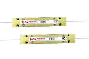
The FBG Array is a collection of Bragg gratings inscribed on a single optical cable. It can handle long-term monitoring as well as multi-point monitoring. It can improve system stability and reliability while also simplifying the system. Contact DK Photonics to personalize the FBG array according to you.
What is a Fiber Collimator? Why is it needed?

Tell us the name of one common thing that you can find in various high-power components such as high-power optical isolators, fiber circulators, fiber optic attenuators, and CWDM/DWDM modules. All these components have one thing in common and that is called a high-power fiber collimator. In this blog, we will discuss high-power collimators in brief. So, if you want to know what these are and why they are needed, keep reading till the end.

What is a fiber collimator?

The meaning of the term “collimate” means to make light rays accurately parallel. Hence, a fiber collimator is a fiber optic component that is used to help change the diverging light from a point source into a parallel beam.

In other words, a fiber collimator is a simple module that consists of fiber and a lens and its basic function is to produce parallel beams.  

Fiber collimators are used to collimate the light at the fiber end and can also be used to couple light beams between two fibers. During the designing process of fiber collimators, utmost attention is given to the accurate adjustment of the fiber and lens so that parallel beams can be obtained.

Another thing you need to know is that the stronger the signal strength the higher the efficiency of the fiber collimator. And the fiber collimators that can handle a huge amount of power are categorized as high-power components.

An efficiently designed high-power collimator is characterized by low insertion loss, high-power handling capability, excellent temperature stability, and small beam convergence. Hence, it is considered an ultra-reliable device.

What is the need for fiber collimators?

In fiber optics applications, it is often necessary to transform the light output from an optical fiber into a collimated beam. For that, a simple collimation lens is considered sufficient. But the end of the fiber must be firmly fixed at a distance from the lens that is usually equal to the focal length. Thus, to make this more convenient in practice, a fiber collimator is used in fiber optics applications that require a collimated beam.

Fiber collimators can also be used for launching light from a collimated beam into a fiber or for fiber-to-fiber coupling where light from the first fiber is collimated and then focused into the second fiber by another collimator.

Another application of fiber collimators is the combination with a back-reflecting mirror and an additional element to achieve desired effects. For instance, you can insert a Faraday rotator to obtain a Fiberized Faraday mirror.

Other major applications of high-power fiber collimators are fiber lasers, fiber amplifiers, instrumentation, and test and measurement.

Applications of optical passive components

A passive optical network is a multi-premises point-to-multipoint network design that enables the providers of communication services to serve several consumers via the same connection. During the activities, no active components are required for conversion of electrical-to-optical or optical-to-electrical. There are a variety of optical passive components available in the market which include optical switches, optical isolators, optical couplers, optical circulators, optical connectors, optical splitters, optical filters, optical, and optical add/drop multiplexers. Optical passive components are found to be a viable answer for today’s telecommunication requirements.

But how are these optical passive components applied? Well, there are various applications of optical passive components. We have listed down the most common types of optical passive components and their application:

Optical coupler/splitter 

The most common optical passive components used for multi-demultiplexing of the wavelength of optical signals are optical couplers/splitters. Optical splitters are utilized for splitting the light signals in multiple fibres whereas optical are meant for integrating the signals arrived from various fibers. The optical coupler and optical splitter are quite similar types of optical passive components. However, the basic difference in their functionality depends on the requirement of the connection and the end-use of the component in input or output. 

Optical connector 

Optical connectors, also known as fiber optic connectors, are generally used to link two optical fibers, cables, or devices temporarily. Manufacturers have developed a variety of optical connectors in optical passive components to fulfill a variety of communication requirements. LC, FC, SC, ST and MTRJ styles of connections are the most common types of optical connectors. 

Optical filter 

An optical filter is a device used for multiplexing/demultiplexing the wavelength with a thin dielectric layer that allows the user to add or subtract a specified wavelength throughout fiber communication. It is mostly used for filtering out a particular wavelength in the middle of fiber according to preset parameters.

We now have a quick and efficient way of data transport due to optical fiber networking. To achieve optimum durability, efficiency, and monetary effectiveness in an optical network, a variety of optical components are used. Optical passive components play a critical role in establishing successful fiber connections.

Optical Attenuator

Optical Attenuator is a term used to describe a device that reduces the intensity of light transmitted. It is employed in the following situations:

  • Keep receivers from being saturated.
  • Ensure that wavelength intensity is balanced.
  • Equalize the strength of the nodes.

There are majorly four types of optical attenuators available in the market for balancing power in fiber communication, named fixed attenuators, variable attenuators, in-line attenuators, and plug-in attenuators.  

Optical switch 

These are devices used for governing the connection between ports meant for output and input. They’re mostly used for:

  • Remote monitoring of an optical fiber network
  • Multiplexing transplantation
  • System for monitoring optical paths
  • Sensory system based on optical fibers
  • Testing of optical devices

Choose the best optical passive components for your fiber networks and ensure better results. 

What are Fiber Bragg grating sensors? What are their uses and applications?

Fiber Bragg Grating (FBG) based sensors are one of the most popular optical fiber sensors these days because they are quite easy to install, don’t get influenced by electromagnetic interferences, and can work well even in highly explosive atmospheres. In this blog, we will walk you through what Fiber Bragg grating-based sensors mean and what uses and applications the FBG-based sensors have.

What are Fiber Bragg grating sensors?

Fiber Bragg grating is a small-size optical fiber that consists of a pattern of many reflection points that reflect particular wavelengths in the direction of the light origin and transmit all others. Based on the principle of Bragg diffraction, it is a progressive optical passive component that looks like a normal optical fiber but acts as a sensor that converts energy from mechanical into optical and electrical.                                                                                                                                                                        

FBG sensors are simple optical sensing elements that can be photo-imprinted in optical fibers. These are wavelength modulated sensors that help detect physical parameters such as strain, temperature, pressure, humidity, vibration, and others depending on the changes in the wavelength.

What makes FBG sensors better than their counterparts?

FBG sensors come with many features and qualities that one can’t get from ordinary optical sensors. Some of these are:

  • High sensing capability
  • High stability and reliability
  • Energy-efficient and cost-effective
  • Easy installation and customized length
  • Immunity to electromagnetic interferences
  • Immunity to radio frequency interferences
  • Suitable for highly explosive environments

What is the use of Fiber Bragg Grating sensors?

  • Fiber Bragg grating sensors can be used as inline optical fibers to block certain wavelengths. Apart from this, they can also be used as wavelength-specific reflectors.
  • Since FBG sensors are ideal wavelength-selective components, they can be used where detection of multiple sensing parameters is required.
  • FBG sensors are also widely used for monitoring composites that are subjected to impact.
  • These optical sensors can help measure the internal strain of the host by evaluating the shift in the reflective wave peak’s wavelength.
  • FBG-based sensors when located even too close to impact site can detect residual strains from an impact that C-scan and visual inspection fail to detect.
  • An array of embedded FBG sensors can predict the location of damage as well.
  • FBG sensors are also used for vibration sensing when they are placed intimately in contact with the vibrating object.
  • BG sensors can also help in acoustic sensing of ultrasonic waves not only in bulk materials but also in liquids.
  • These optical sensors have also been used for monitoring ultrasound in vivo.
  • Femtosecond laser-imprinted FBGs are thermally stable, and, thus, are potential candidates for high-temperature sensing applications.
  • These sensors can also be used for intelligent textiles as they can be integrated into flexible orthoses to determine a patient’s requirements and generate feedback.

What are the applications of Fiber Bragg Grating (FBG) sensors?

FBG sensors are the optical passive components that have so much potential to be used in a myriad of applications across different industries. While some applications are widely common, many areas remain yet to be explored when it comes to utilizing the powerful capabilities of FBG sensors.  Some of the common applications of FBG sensors include:

  • ASE filtering
  • Wavelength filtering
  • Environmental monitoring
  • Power line monitoring
  • Structural health monitoring
  • Instrumentation applications, such as seismology
  • Pressure sensors for extreme environments
  • Downhole sensors in oil and gas wells to measure the effects of temperature, external pressure, seismic vibrations, and inline flow measurement

Most FBG sensors are used in single-mode fibers and their modeling is relatively simple. When buying FBG sensors online, do your research properly as FBG sensors are available in a variety of options, and picking the right one is important to achieve the desired performance and functionality.

Do parasitic signals affect the performance of pump laser diodes?

Parasitic signals are usually undesirable elements and most often unavoidable too. When parasitic elements are encountered in sensitive components like pump laser diodes, you need to take precautions to get rid of these parasitic signals. Otherwise, parasitic signals can lead to crosstalk, interference, and unreliable operation. That’s where pump laser protectors come into the picture.     

Why do we need to protect the pump laser from parasitic signals?

Pump lasers and pump laser diodes are the components that require having high reliability. However, if we keep allowing parasitic signals to reflect into the laser, it can lead to errors, performance degradation, and unstable operation. Therefore, pump laser protectors play a great role in ensuring the safe and reliable operation of pump laser diodes.

Now, you must be wondering what exactly pump laser protectors are. Let’s find out.

What are pump laser protectors?

Pump laser protectors are passive components that are specifically designed to protect the laser’s center wavelength by preventing parasitic signals from being reflected back in the laser. Besides, they also allow maximum transmission from discrete pump laser diodes that are fiber-coupled. Since pump laser protectors filter out parasitic signals by blocking them, these passive components are also known as pump laser filters.

What are the applications of pump laser protectors?

Pump laser protectors find their use in a variety of applications, such as:

  • Fiber amplifiers: Can be used with fiber amplifiers that are used to boost optical signals directly without converting them into electrical signals.
  • Fiber laser: Can be utilized with solid-state type laser that utilizes optical fiber as the gain medium and is widely used for material processing, telecommunication, etc.
  • Testing: It is not easy to distinguish the effects of parasitic signals, which made it many times difficult to measure the performance of certain fiber optic components. Pump laser protectors can help with testing.
  • Instrumentation: Can help achieve a high signal to noise ratio

What Properties Do Pump Laser Protectors Have?

When buying pump laser protectors, you should verify if they:

  • Have low insertion loss
  • Can handle high power
  • Offer high isolation
  • Are highly reliable
  • Have excellent temperature stability
  • Are highly affordable

Where Can I Buy High-Quality Pump Laser Protectors (Filters)?

If you are looking to buy high-quality pump laser protectors, look no further than DK Photonics. We can provide you with pump laser protectors in different specifications. Even if you can’t find pump laser protectors with the specifications you are looking for, you can place a custom order and we will facilitate you with it. All you need is to contact us and share your custom specifications.  

Fundamental Things You Need To Know About Passive Electronic Components!!

Regardless of whether you know it or not, one of the crucial factors that distinguish kinds of electronic components from one other is if they are active or passive. Although, tons of individuals are still unsure about the difference! On the off chance, if you also fall under the same category of individuals, there is nothing to feel embarrassed as we have got you covered.

Mentioned below is the difference between active and passive components. So, keep reading.

The Difference

Active components: These are crucial parts of a circuit that entirely depends on an external power source to manage or modify electric signals. For your better understanding, active components such as transistors and silicon-controlled rectifiers (SCRs) utilize electricity to handle electricity.

Passive components: High power components such as resistors, transformers, and diodes do not consume external power source to function precisely. These high power components utilize some different properties to manage the electrical signal, as an outcome, they only need the current going via the connected circuit. Resistors hinder the flow of electrons without transferring more electricity into the system. The two precisely explained high power components examples are listed below.

1. Capacitors: A capacitor also called as condenser is a passive two-terminal electronic component that is utilized for storing energy electro-statically in an electric field.  There are various forms of practical capacitors, yet each and every one still contain at least two electrical conductors that are separated by an insulator aka dielectric. The conductors can be in the form of thin films, sintered beads of metal, foils or conductive electrolyte. The non-conducting insulators are used to double the charge capacity of condenser. An insulator can be made of glass, ceramic, plastic film, air, vacuum, paper, mica, oxide layer etc. In plenty of electrical devices, capacitors/ condensers are widely used as parts of electrical circuits. Unlike a resistor, an optimal condenser does not squander energy. Rather than dissipating, a capacitor stores energy in the state of electrostatic field between its plates.

2. Resistors: A resistor is a passive two-terminal electrical component that applies electrical intransigence as a circuit element. Resistors are generally used to lessen the current flow, and, at the same time, they are also used for lowering the voltage levels within circuits. In electronic circuits, there are utilized to restrict current flow, adjust signal levels, bias active elements, terminate transmission lines and the list is endless. High-power resistors that are capable of dissipating loads of watts of electrical power can also be used as part of motor controls, in power distribution systems, or as test loads for generators. In addition to this, resistors may comes with fixed resistances that only get changed with a cold temperature, time or operating voltage. Also, variable resistors can be used to adjust circuit elements.

So, these were some of the most imperative things that you should know. For any further clarification and information, please get in touch with us whenever you want.

What is Wavelength-Division Multiplexing and Its Benefits?

A technical solution that permits the combination (“mux”) of several separate light wavelengths (signals/channels) from different lasers on a single fiber utilizing a passive component for transmission to another site is called Wavelength-division Multiplexing (WDM).

The WDM components then demultiplex the combined wavelengths at the receiving location and route them to their appropriate receivers.

The Main Components of WDM System

In a WDM system, there are two different types of approaches:

  • Dual-fiber unidirectional transmission
  • Single-fiber bidirectional transmission.

The simultaneous transmission of multiple optical channels on a fiber propagating in one direction is known as dual-fiber Unidirectional WDM.

There are separate wavelengths that convey different paths across an optical fiber. At the transmitting end, these signals are combined for transmission across the fiber and demultiplexed to complete multiple paths at the receiving end.

It is necessary to use a second optical fiber for the opposite direction of the transmission. And since the transmission takes place in both directions, it is vital to use two optical fibers.

Bidirectional WDM is the simultaneous transmission of optical channels in both directions on a fiber, with the wavelengths employed segregated to achieve full-duplex communication between the two sides.

The standard components of a WDM system are:

  • The network management system
  • Optical transmitter
  • Optical relay amplifier
  • Optical receiver
  • Optical monitoring channel are.

The WDM system’s overall structure

Transceivers, WDM wavelength division multiplexers, patch cords, and dark fiber components make up the basic WDM system.

WDM system

The multiplexer and demultiplexer are critical components in the WDM technology, and their performance is crucial for the system’s transmission quality.

What are the benefits of using WDM Technology?

  1. Large Capacity

WDM’s main advantage is that it can fully utilize the optical fiber’s bandwidth resources and enhance data transmission capacity without requiring changes to the current network architecture. It allows an optical fiber’s transmission capacity to multiply a single wavelength.

2. Excellent Compatibility

WDM has a wide range of signal compatibility. Each wavelength is independent of the others and does not interfere with each other when transmitting signals with diverse qualities such as pictures, data, and sound to ensure transmission transparency.

3. Flexibility, Cost-effectiveness, and Dependability

WDM technology enables the addition of new channels as needed without disrupting the existing network, making upgrades convenient.

There is no need to replace the optical cable line when updating or increasing the network. New enterprises can be added or superimposed by adding wavelengths.

Large-capacity long-distance transmission can conserve optical fibers and 3R regenerators, lowering transmission costs dramatically.

4. Wavelength Routing

WDM is one of the most critical technologies for implementing all-optical networks. The up/down and cross-connection of various telecommunication services can be implemented by altering and adjusting the wavelength of the optical signal on the optical path.

A reputable designer and manufacturer of high-quality optical passive components can provide a comprehensive portfolio of WDM solutions tailored to your unique needs, allowing you to achieve system goals in the most efficient way possible.

Top Features and Applications of In-line Polarizers

When it comes to data transmission and light guiding applications, you can rely on fiber optic cables. They play a vital role in constituting a complete network that is used for transmitting data over long distances at a wide range bandwidth. Fiber optic technology is considered to be ideal for medical, networking, military, electronics, communications, and various other applications.

Though light waves (polarized or unpolarized), can travel through optical fibers with ease, losses are experienced with unpolarized light. Unpolarized light waves travel with significant losses and distortions especially for long distances and this can be detrimental for transmitting information.

To avoid such issues, fiber optic polarizers are used because they can provide the strongest and cleanest output signal.

In this blog, we will explore what these fiber optic polarizers are, what features they have, and where these devices are used.

What is Fiber-Optic Polarizer?

Fiber optic polarizers are small pieces of cable placed in-line with fiber that helps in polarizing the incoming light wave/signal. Fiber with controlled polarization yields output with maximum intensity and bandwidth without disturbing the velocity.

The term that is quite popular with fiber optic technology is in-line polarizer.

In-line polarizers are specially designed to pass the light with specific polarization while blocking the orthogonal polarization. They help in the conversion of unpolarized light into polarized light with a high extinction ratio.

Generally, the standard configuration used for these polarizers is single-mode fiber for input and polarization-maintaining fiber for output.

Features of In-line Polarizers

The salient features that define high quality in-line polarizer are as follows:

  • Low insertion loss
  • Very small in size
  • High extinction ratio
  • Excellent reliability
  • High power handling ability
  • Very affordable
  • Superior performance

Available Versions of In-line Polarizers

The two versions of in-line polarizers are available in the market:

Pigtailed In-line Polarizer

This version of in-line polarizer comes with ~1 m long fiber pigtails with a 900 µm tube. The benefit of using pigtail in-line polarizers is that they are more economical and provide the user with added length for use in the fiber optic system.

Bulkhead In-line Polarizer

This in-line polarizer version is widely famous for being rugged. It does not have any pigtails. Since there are no pigtails, this makes polarizer handling easier. There is no need to worry about handling fragile fibers. Besides, it comes with the advantage of removing polarization disturbances caused by pigtails.

Applications of In-line Polarizers

  • Analysis of polarization
  • Monitoring and control of polarization
  • SNR (Signal-to-Noise Ratio) Monitoring
  • PMD (Polarization Mode Dispersion) Monitoring
  • PER (Polarization Extinction Ratio) Monitoring
  • Polarization interferometry
  • Spectrum filtering and control
  • Fiber laser mode-locking

If you also need in-line polarizer for your application or have any query related to it, contact a reputed online in-line polarizer supplier to ensure high quality or gain insights.

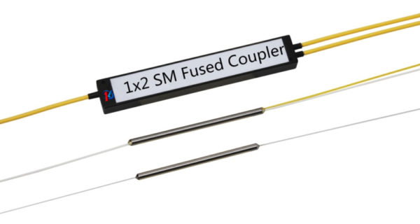
How to Buy Optical Fused Coupler: All You Need To Do

Optical coupler is something most important for phonics devices and systems that are meant to combine or split light signals into fibers. The couplers can be either active or passive devices. The passive redistributes the signal without optical-to-electrical conversion while Active couplers split or combine the signals electronically.

When it comes to buying Optical Fused Coupler, there are some crucial factors that you should base your decision.

What you need them for

Before you start searching for Optical Fused Coupler suppliers, get to know where you are going to use them. As each coupler has different features which make them perfect for some certain application, if you know your need, you can choose the coupler equipped with the features essential to cater to your needs.

How they work

A basic fiber optic coupler has two points: N input ports and M output ports. These points will typically range from 1 to 64. But generally, these devices have four-port. How they work depends on the distributed coupling between two individual waveguides in close proximity, and this makes the power gradually transfers between modes which are supported by these waveguides.

 Four ports fiber optic coupler works like this. When light enters into the port 1, it splits into output ports which are port 3 and port 4.  And the port 2 functions in the same way. Sometimes, either port 1 or port 2 remains unused. In such case, the fiber optic coupler acts as a Y or T coupler.

As we have learnt that fiber optic coupler is used to couple or split light, so the coupler is also called fiber optic splitter. The term is used as it, the coupler, splits the light signal.

Where to buy

As you, now, know what you need a coupler for and how a coupler works, you are able to decide on the optic fused coupler. But where you buy it?

There are many fused optical manufacturers and suppliers in China. They make a wide range of couplers for various applications. But choose a manufacture that best suits you.

Check for their clients. This will help you know how they will cater to your needs. If they serve needs of businesses like yours, they are more likely to meet your expectation. Also, make sure if they provide customization. Because. There are many like DK Phontonics that also offer to customize the coupler to meet particular requirements. But make sure the prices offered are reasonable for the quality you get.

DWDM Mux/Demux: A Quick Look at Everything, Features to Applications

Wavelength division multiplexing (WDM) is a kind of technology, commonly used in optical communications. It works by combing multiple wavelengths to transmit signals on a single fiber. CWDM and DWDM mux/demux are the essential part of this process.

WDM mux and demux have several different ports, each with a different function to perform.  We will discuss each of them, looking at their applications.

A Sneak Peak into Ports on WDM MUX/DEMUX

There are five major ports used on the MUX/DIMUX. Have a detailed look at each of them below.

Line Port

Sometimes, also called common port, this is the one of the most important ports that must be on CWDM and DWDM Mux/Demux. It helps to connect the outside fibers often marked as Tx and Rx to the Mux/Demux unit. All the WDM channels are multiplexed and demultiplexed over this port.

Channel Port

Channel port is another must-have port, which transmits and receives signals on specific WDM wavelengths. Because of this port, CWDM Mux/Demux can support up to 18 channels from 1270nm to 1610nm with a channel space of 20nm. While DWDM Mux/Demux uses wavelengths anything between 1470nm and 1625nm, services or circuits can be added in any order to the Mux/Demux unit.

Monitor Port

This port on CWDM and DWDM Mux/Demux helps test the dB level of the signal. And the best thing about the port is that service is not interrupted during the signal test, which provides users with the ability to monitor and troubleshoot networks. If your Mux/Demux is a sing-fiber unit, use the monitor port which is simplex one.

Expansion Port

This port aims to expand more wavelengths or channels to the network. Connecting the expansion port with the line port of another Mux/Demux supporting different wavelengths, you can increase the network capacity. However, not every WDM Mux/Demux has an expansion port.

1310nm and 1550nm Port

These are wavelengths ports that enable optical transceivers, especially the CWDM and DWDM SFP/SFP+ transceiver to support long runs transmission. Using these ports, you can add 1310nm or 1550nm wavelengths into existing WDM networks by connecting with the same wavelength optical transceivers.

Application Cases of Different Ports on WDM MUX/DEMUX

While WDM Mux/Demux have many different ports, you do not need to use all of them at the same time. Here are some examples of their applications.

  • Use 8 Channels CWDM Mux/Demux with Monitor Port where two switches/routers are connected over CWDM wavelength 1511nm.
  • Achieve 500Gbps at Existing Fiber Network with 1310nm Port
  • Stack Two CWDM MUX/DEMUX Using Expansion Port

As we know different ports on the CWDM and DWDM Mux/Demux have different functions, you should buy DWDM Mux/Demux with ports that precisely meet your requirements. If you are looking for DWDM Mux/Demux for the best price, you can trust, DK Photonics – a leading supplier optical passive competent in China.