What is a fiber optical attenuator? Why is it used?

Fiber optic attenuators are small passive devices designed to reduce the strength of an optical signal. For those who are unfamiliar, attenuation refers to the rate at which the light or signal loses its strength. Optical attenuators are available in different types, including, fixed, step-wise variable, and continuously variable optical attenuators.

When people learn what fiber optic attenuators means, they typically wonder why anyone would want to introduce attenuation purposely on a fiber optic network. If you are also the one, then keep reading.

Why are fiber optical attenuators useful? Why do you need to accentuate signals?

There are many scenarios in which you need a mechanical variable optical attenuator. For instance, in a multi-wavelength fiber optic system, you need to equalize the strength of optical channel so that every channel has similar power levels. This requires you to reduce the strength of optical signals so that they lower down to match the channels with lower power.

Another example includes the system where received optical power is so much strong that it saturates the receiver. In this case, you will also need an optical attenuator to ensure that the receiver can detect the signal correctly.                                                                                                                                                                    

Hence, you can say that they are proved to be very useful in conditions when the signal arriving at the receiver is too strong and can overpower the receiving equipment.

But, why does a transmitter send too strong signals? This often occurs due to a mismatch between transmitters and receivers. Sometimes, it happens because the media converters are meant to be used for much longer distance than they are currently being used for.

Apart from preventing the receiver from being overwhelmed by too strong signals, optical attenuators are also widely used for stress testing a network link by reducing the signal strength incrementally until the optical link fails. It helps in determining the signal’s existing safety margin.

What are the different types of fiber optical attenuators?

While fiber optical attenuators are typically used in single-mode circuits because of the use of stronger lasers for distance transmission, you can also find multi-mode attenuators.

Male to female attenuators are the most common type of attenuators. They are also known with other names, such as plug-style or buildout style. These attenuators are designed to mount on one end of a fiber optic cable so that the cable can be plugged into the receiving equipment or panel.

There are also female to female attenuators, also called bulkhead attenuators that are often mounted in patch panels or used to connect two optic cables together.

Apart from these, there are variable optical attenuators that are highly useful for testing applications but are more expensive than other types of attenuators. Thus, before you place any order for fiber optical attenuator, you must check which type of attenuator you need and for which application.                                                                                                                                                                 

Field-Terminated Fusion Splice-On Connector-North American Market Forecast

According to ElectroniCast, the quantity of field-terminated fiber optic splice-on connectors in North America will increase at an explosive annual rate of 41.9% …

ElectroniCast Consultants, a leading market research & technology forecast consultancy addressing the fiber optics communications industry, today announced the release of a new market forecast of the consumption of field terminated fiber optic fusion splice-on connectors in North America.

Fusion_Splice_on_Connector

Field terminated fiber optic fusion Splice On Connectors (SOC) are installed for rapid repairs or for limited space situations where pre-terminated fiber cabling may be difficult, such as when the cable assembly needs to pass through small openings such as conduit.  The splice-on connectors are an option when the precise length of the optical fiber link is not pre-determined and a field-installed termination solution is required, such as in Fiber to the Home (FTTH) and other communication applications.

Last year, 306-thousand field-terminated fiber optic fusion splice-on connectors were installed in non-OEM applications in North America.  The number of connectors is forecast to increase at an explosive rate of 41.9% per year, reaching 2.49 million units in 2020.  Market forecast data in this study report refers to consumption (use) for a particular calendar year; therefore, this data is not cumulative data.

The Telecommunications application category is forecast to maintain the leadership in relative market share through the year 2018, until the Premises Networks application category is set to capture the lead.  Telecommunication use is forecast for 35.5% annual growth in quantity (2014-2020), mainly driven by access optical fiber deployment.  The Cable TV application is also driven by the use of connectors for FTTH (Home) and FTTB (Building/MDUs – Multiple Dwelling Units).

The market forecast segments the connectors by single-mode and multimode optical fiber, as well as into the following types: MPO, LC, FC, ST, SC, and other.  The use of single mode fiber optic field-terminated fusion splice-on connectors in North America is forecast to increase from 173.8-thousand units in 2014 to 1.49 million in 2020.  Multimode fiber is best suited for use in short lengths, such as those used in datacom and specialty networks and in 2020, multimode connectors are expected to reach 1-million units.

“In 2014 in North America, 4.3-thousand new fusion splicers were brought into Premises Datacom, and the use of field terminated fusion splice on connectors is a major market driver for the use of fiber optic fusion splicers used in premises network applications, the data center (DC) and longer link length datacom cable installations,” said Stephen Montgomery, Director of the ElectroniCast market study.

“The SOCs are emerging as a viable alternative to pre-terminated fiber optic cables (pigtail and cable assemblies/ patch cords).  Also, based on primary research interviews with network planners and installers, we are finding that field terminated fusion splice-on connectors are rapidly being accepted as a go-to solution.  With SOCs, communication network technicians can install reliable cable links with exact lengths, eliminating cable shortness or excess slack that is typically a result with the pre-terminated cable solution,” Montgomery added.

Tags: CWDM Multiplexer, DWDM Multiplexer,19″ rack mount chassis CWDM, ABS plastic box, CWDM MUX/DEMUX Module,  LGX CWDM Module,8CH CWDM Module, 16CH CWDM Module

Testing Fiber Optic Splitters Or Other Passive Devices

A fiber optic splitter is a device that splits the fiber optic light into several parts by a certain ratio. For example, when a beam of fiber optic light transmitted from a 1X4 equal ratio splitter, it will be divided into 4-fiber optic light by equal ratio that is each beam is 1/4 or 25% of the original source one. A Optical Splitter is different from WDM. WDM can divide the different wavelength fiber optic light into different channels. fiber optic splitter divide the light power and send it to different channels.

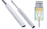
Most Splitters available in 900µm loose tube and 250µm bare fiber. 1×2 and 2×2 couplers come standard with a protective metal sleeve to cover the split. Higher output counts are built with a box to protect the splitting components.

Testing a coupler or splitter (both names are used for the same device) or other passive fiber optic devices like switches is little different from testing a patchcord or cable plant using the two industry standard tests, OFSTP-14 for double-ended loss (connectors on both ends) or FOTP-171 for single-ended testing.

First we should define what these passive devices are. An optical coupler is a passive device that can split or combine signals in optical fibers. They are named by the number of inputs and outputs, so a splitter with one input and 2 outputs is a 1×2 fiber splitter, and a PON splitter with one input and 32 outputs is 1×32 splitter. Some PON splitters have two inputs so it would be a 2X32. Here is a table of typical losses for splitters.

Splitter-Ratio

Important Note! Mode Conditioning can be very important to testing couplers. Some of the ways they are manufactured make them very sensitive to mode conditioning, especially multimode but even singlemode couplers. Singlemode couplers should always be tested with a small loop in the launch cable (tied down so it does not change and set the 0dB reference with the loop.) Multimode couplers should be mode conditioned by a mandrel wrap or similar to ensure consistency.

Let’s start with the simplest type. Shown below is a simple 1X2 splitter with one input and two outputs. Basically, in one direction it splits the signal into 2 parts to couple to two fibers. If the split is equal, each fiber will carry a signal that is 3dB less than the input (3dB being a factor of two) plus some excess loss in the coupler and perhaps the connectors on the splitter module. Going the other direction, signals in either fiber will be combined into the one fiber on the other side. The loss is this direction is a function of how the coupler is made. Some couplers are made by twisting two fibers together and fusing them in high heat, so the coupler is really a 2X2 coupler in which case the loss is the same (3dB plus excess loss) in either direction. Some splitters use optical integrated components, so they can be true splitters and the loss in each direction may different.
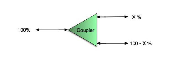
optical coupler

So for this simple 1X2 splitter, how do we test it? Simply follow the same directions for a double-ended loss test. Attach a launch reference cable to the test source of the proper wavelength (some splitters are wavelength dependent), calibrate the output of the launch cable with the meter to set the 0dB reference, attach to the source launch to the splitter, attach a receive launch cable to the output and the meter and measure loss. What you are measuring is the loss of the splitter due to the split ratio, excess loss from the manufacturing process used to make the splitter and the input and output connectors. So the loss you measure is the loss you can expect when you plug the splitter into a cable plant.

To test the loss to the second port, simply move the receive cable to the other port and read the loss from the meter. This same method works with typical PON splitters that are 1 input and 32 outputs. Set the source up on the input and use the meter and reference cable to test each output port in turn.

What about the other direction from all the output ports? (In PON terms, we call that upstream and the other way from the 1 to 32 ports direction downstream.) Simply reverse the direction of the test. If you are tesing a 1X2 splitter, there is just one other port to test, but with a 1X32, you have to move the source 32 times and record the results on the meter.
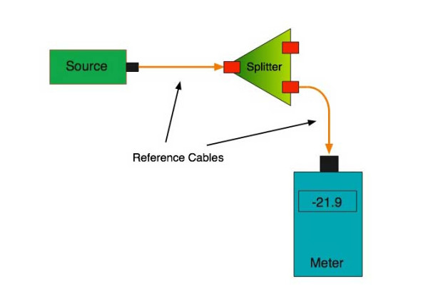
fiber-splitter

What about multiple input and outputs, for example a 2X2 coupler? You would need to test from one input port to the two outputs, then from the other input port to each of the two outputs. This involves a lot of data sometimes but it needs to be tested.

There are other tests that can be performed, including wavelength variations (test at several wavelengths), variations among outputs (compare outputs) and even crosstalk (put a signal on one output and look for signal on other outputs.)

Once installed, the splitter simply becomes one source of loss in the cable plant and is tested as part of that cable plant loss for insertion loss testing. Testing splitters with an OTDR is not the same in each direction.

Other Passive Devices

There are other passive devices that require testing, but the test methods are similar.

Fiber optic switches are devices that can switch an input to one of several outputs under electronic control. Test as you would the splitter as shown above. Switches may be designed for use in only one direction, so check the device specifications to ensure you test in the proper direction. Switches may also need testing for consistency after multiple switch cycles and crosstalk.

Attenuators are used to reduce signal levels at the receiver to prevent overloading the receiver. There is a page on using attenuators that you should read. If you need to test an attenuator alone, not part of a system, use the test for splitters above by using the attenuator to connect the launch and receive cables to see if the loss is as expected.

Wavelength-division multiplexers can be tricky to test because they require sources at a precise wavelenth and spectral width, but otherwise the test procedures are similar to other passive components.

Fiber optic couplers or splitters are available in a wide range of styles and sizes to split or combine light with minimal loss. All couplers are manufactured using a very simple proprietary process that produces reliable, low-cost devices. They are physically rugged and insensitive to operating temperatures. Couplers can be fabricated in custom fiber lengths and/or with terminations of any type.

DK Photonicswww.dkphotonics.com  specializes in designing and manufacturing of high quality optical passive components mainly for telecommunication, fiber sensor and fiber laser applications,such as PLC Splitter, WDM, FWDM, CWDM, DWDM, OADM,Optical Circulator, Isolator, PM Circulator, PM Isolator, Fused Coupler, Fused WDM, Collimator and Polarization Maintaining Components, Pump Combiner, High power isolator, Patch Cord and all kinds of connectors.

Fiber Optic Collimator Lens Assembly Global Market Forecast-DK Photonics

Fiber optic collimator lens arrays are forecast with strong value-based growth rates of more than 45% per year (2013-2018)…

Aptos, CA (USA) – May 9, 2014 —ElectroniCast Consultants, a leading market research & technology forecast consultancy addressing the fiber optics communications industry, today announced the release of a new market forecastof the global market consumption and technology trends ofcommercial (non-military) fiber optic collimating lens assemblies, which are used in optical communication applications.

The market study covers single lens assemblies, 2-12 lens arrays, and arrays with more than 12 lenses. Both of the lens array categories are forecast with strong growth rates of more than 45% per year (2013-2018).  Single lens fiber optic collimator assemblies hold the global market share lead in the selected optical communication applications covered in the ElectroniCast study.

“Collimator lenses (and lens assemblies) are used in a variety of photonic products; however this market study forecasts the use of micro-sized collimator lens assemblies, which are used specifically in optical communication components/devices. Fiber optic collimator lens assemblies serve as a key indicator of the growth of the fiber optic communication component industry,” said Stephen Montgomery, Director of the Fiber Optic Component group at the California-based consultancy.

ElectroniCast defines lens assemblies as lenses (one or more), which are attached to an optical fiber or fitted/attached into (or on) a planar waveguide/array substrates or other device(s) for the purpose of collimating light for optical fiber communication.

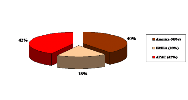
The global consumption of fiber optic collimator lens assemblies, which are used in commercial optical communication applications, reached $264.2 million last year in 2013 and is forecast to reach $298.4 million this year (2014), an increase of 12.9%.    The American and APAC regions are forecast to remain relatively close together in relative consumption value market share.  The Europe, Middle East and Africa regional segment (EMEA) is forecast with the fastest average annual growth rate during the forecast period.  Market forecast data in the ElectroniCast report refers to consumption (use) for a particular calendar year; therefore, this data is not cumulative data.

Fiber optic collimator lens assemblies are widely used to covert a divergent output laser beam from a fiber or waveguide into an expanding beam of parallel light; therefore, they are used in a variety of optical communication components, such as: modulators, attenuators, transmitters, pump laser modules, switches/optical cross connects, wavelength selective switches, ROADMs, isolators, circulators, expanded-beam connector assemblies, optical filter modules, DWDM, tunable filters, optical sensors, optical signal processing, integrated/hybrid packaged modules, and other active and passive components and devices.

The Asia Pacific region is currently the leader in consumption value of the fiber optic collimator lens assembly market …

Fiber Optic Collimator Lens Assemblies

Global Market Share (%), By Region (Value Basis, Estimate – 2014)

Fiber Optic Collimator

DK Photonicswww.dkphotonics.com  specializes in designing and manufacturing of high quality optical passive components mainly for telecommunication, fiber sensor and fiber laser applications,such as WDM, FWDM, CWDM, DWDM, OADM,Optical Circulator, Isolator, PM Circulator, PM Isolator, Fused Coupler, Fused WDM, Collimator, Optical Switch and Polarization Maintaining Components, Pump Combiner, High power isolator, Patch Cord and all kinds of connectors.

Optical Isolators Global Market Forecast-DK Photonics

According to ElectroniCast, optical isolator value in Telecommunications is forecast to increase 19.6% this year…

Aptos, California (USA) – April 29, 2014  —ElectroniCast Consultants, a leading market research & technology forecast consultancy addressing the fiber optics communications industry, today announced the release of a new market forecastof the global consumption of optical isolators in optical communication and specialty applications.

According to ElectroniCast, the worldwide optical isolator consumption was led by Telecommunication applications in 2013 with a 70 percent market share or $349.7 million, and is forecasted to increase 19.6 percent in value to $418.2 million this year (2014).  Market forecast data in this study report refers to consumption (use) for a particular calendar year; therefore, this data is not cumulative data.

Optical isolators are devices that allow light to be transmitted in only one direction. They are most often used to prevent any light from reflecting back down the optical fiber, as this light would enter the source and cause backscattering and feedback problems. This is especially important for high data rate transceivers and transponders, or those devices requiring long span lengths between transceiver pairs. Optical feedback degrades signal-to-noise ratio and consequently bit-error rate.

“Continuing demand for upgrading communication networks to accommodate rapidly increasing bandwidth requirements will drive the steady consumption of optical fiber links. Optical isolators are used in with high-speed transmitters that are required to transmit longer distances and/or multiple wavelength transmitters,” stated Stephen Montgomery, Director of the Fiber Optics Components group at ElectroniCast Consultants.

Optical isolators are not widely used in Private Enterprise applications; however, worldwide use of fiber optic isolators in Cable TV controlled device deployments are forecast to grow significantly in value at an annual rate of 8.8 percent (2013-2018), as optical fiber is deployed closer to the home driven by multi-media applications.

Optical isolator units are used in a variety of Military/Aerospace applications requiring rigorous testing and harsh environment fiber optic (HEFO) certification to ensure reliability and performance.  Laser-based fiber optic technology incorporating optical isolators are used in a wide variety of air, sea, ground, and space applications.

A major user-group within the Specialty application category is Laboratory/R&D.  Optical isolators are used for noise reduction, medical imaging, pulse selection for mode locked lasers, sensing, regeneration switches, disc master, optical trapping, phase shifters, frequency modulation spectroscopy and general shuttering. The optical isolators are also used in sensing for industrial, structures and other many other communication product-oriented manufacturing/test/R&D uses.

“During the forecast period (2013-2018), bandwidth expansion demands will push for new network links, incorporating Metro Core, Metro/Access, Long Haul, Optical Fiber Amplifiers, WDM, OADM and other system-based deployments, which incorporate optical isolators,” Montgomery added.

The American region held the lead in terms of relative market share consumption value of optical isolators in 2013, with nearly 43.4 percent; however the American region is forecast to increase at a slower rate compared to the other regions (2013-2018). The Asia Pacific region (APAC) is forecast to increase in worldwide market share from 39.7 percent in 2013 to with 53.7 percent in 2018.  The Europe, Middle East, African region (EMEA) is forecast to remain in the third-place position, however, increase at a faster annual pace versus the American region.

According to ElectroniCast, the American Region leads optical isolator consumption value…

2013 – Optical Isolator Global Value Market Share (%),

By Region, $498 Million

Source: ElectroniCast Consultants

Optical Isolator Global Value Market Share (%)

DK Photonicswww.dkphotonics.com  specializes in designing and manufacturing of high quality optical passive components mainly for telecommunication, fiber sensor and fiber laser applications,such as PLC Splitter, WDM, FWDM, CWDM, DWDM, OADM,Optical Circulator, Isolator, PM Circulator, PM Isolator, Fused Coupler, Fused WDM, Collimator, Optical Switch and Polarization Maintaining Components, Pump Combiner, High power isolator, Patch Cord and all kinds of connectors.

The Ion exchange process and the Glass choice of the PLC Splitter Chip

Along with development of the optical communication, its good environmental stability and compatibility with fiber, began to widely used optical communication components manufacturing.( Such as self-focusing lens, optical divider, optical amplifier, etc), And extend to the sensing area, (such as: all kinds of biological and chemical sensors , current sensors which is based on fading light waves, etc.)plc splitter

Glass ion-exchange technology has several one hundred years long history, Its earliest used to change the light absorption characteristics of glass, glass coloring,then, the technology is widely used in processing on the surface of the glass surface (such as touch screen add hard processing). Along with development of the optical communication, its good environmental stability and compatibility with fiber, began to widely used optical communication components manufacturing.( Such as self-focusing lens, optical divider, optical amplifier, etc), And extend to the sensing area, (such as: all kinds of biological and chemical sensors , current sensors which is based on fading light waves, etc.)

Current mainstream technology of PLC Splitter chip includes: PECVD technology, flame hydrolysis technology, glass ion exchange technology. Glass principle and technological process of ion exchange technology as shown in figure 1,figure 2. The main process flow flame hydrolysis technology shown in figure 3. The process characteristics of contrast see table 1. From years of use and reliability experiment, the two technologies are used in mass production and the performance is good.The features of PECVD/flame hydrolysis technique are that equipment and raw materials is the existing material, but its process is very complicated, the production cycle is long, the processing tolerance is small; Glass ion exchange technology is characterized by equipment and raw materials need special customized, but its technology is relatively simple, high production efficiency, process tolerance is larger, the chip cost is relatively low.

DK Photonicswww.dkphotonics.com  specializes in designing and manufacturing of high quality optical passive components mainly for telecommunication, fiber sensor and fiber laser applications,such as PLC Splitter, WDM, FWDM, CWDM, DWDM, OADM,Optical Circulator, Isolator, PM Circulator, PM Isolator, Fused Coupler, Fused WDM, Collimator, Optical Switch and Polarization Maintaining Components, Pump Combiner, High power isolator, Patch Cord and all kinds of connectors.

What Is an Optical Attenuator?

LC Plug Type Fixed AttenuatorAn optical attenuator decreases the strength of an optical signal passing through it to a fiber optic cable or open air. The intensity of the signal is described in decibels over a specific distance the signal travels. It is the strength, or amplitude of the signal that changes and not the overall waveform or frequency, so the optical signal remains undistorted for use in the desired application. Optical attenuators are often used in optical communication systems, in which the attenuation, also called transmission loss, helps with the long-distance transmission of digital signals. The most common optical attenuator types include fixed and continuously variable attenuators.

Often installed where signals are transmitted from, an optical attenuator can apply the principle of gap loss so the signal intensity is lowered to the optimal level over a given distance. Attenuators installed elsewhere along the optical fiber will not lower the signal strength enough, but some devices utilize signal absorbing or reflecting components to compensate. An optical fiber connector is often attached to the optical attenuator which typically has an adapter with a female configuration. The attenuator itself usually has a cylindrical or even box-like structural shape which determines the type of equipment in which it can be installed.

The fixed variety of optical attenuator, sometimes found in an electronic circuit, does not reflect light signals to reduce their intensity. It is generally used where the transmission of data needs to be highly accurate. The device’s function is determined by the amount of power it can handle in addition to important variables such as performance versus temperature and frequency range. Most optical attenuators utilize resistors, but a variable optical attenuator uses metal semiconductor field effect transistors or other solid state components. Attenuation intensity is adjustable so the signals in a fiber optic communication system can be changed to accommodate fluctuating power levels, protecting the system from damage.

A variable optical attenuator can be mounted on a printed circuit board, or used in test devices such as an optical power meter. Many attenuators are installed in-line with an optical fiber cable in order to adjust the transmitted signal accordingly. They are sold by many retailers and manufacturers online so one can assess their characteristics by reading the product specifications. Aspects to consider include the average and peak power the device can tolerate, how much attenuation it provides, as well as its overall dimensions and the type of environment it can operate in.

Application of optical communication is still broad prospects

Once the Nortel global leader in fiber optic communications during the Internet bubble in 2000, the money in the acquisition of a large number of optical communications research and the production of small and medium enterprises, the industry has been criticized in the subsequent bankruptcy of Nortel. In fact, Nortel grasp of technology trends, the direction is right, unfortunately, Nortel too hasty, global demand for optical communication was not to such an extent.

But now the situation is very different compared with around 2000. The rapid development of mobile Internet and the widespread popularity of smart mobile terminal equipment, being a huge challenge to the global telecommunications network capacity, transmission speed. The era of “data flood peak to optical communication technology has always been known by the transmission bit of new development opportunities and a huge space. Optical communication technology not only did not fall behind, the contrary, the optical communication industry chain, from fiber optic cable system equipment, terminal equipment to optical devices, a critical period in the comprehensive technology upgrade.

The field of optical communication is a noteworthy event, the National Development and Reform Commission recently organizing the preparation of strategic emerging industries key products and services Guidance Catalogue, which in conjunction with the relevant departments, the optical communication technology and product responsibility and selected emerging industries of strategic focus products.

In fiber optics, including FTTx G.657 optical fiber, broadband long-distance high speed large capacity optical fiber transmission with G.656 optical fiber, photonic crystal fiber, rare earth doped fiber (including ytterbium doped fiber, erbium doped fiber and thulium doped fiber, etc.) the laser energy transmission fiber, and has some special properties of new optical fiber, plastic optical fiber, polymer optical fiber is fully finalists. The upgrade of the fiber optic technology, will bring the data transmission capacity, distance, quality leap.

In the field of fiber access equipment, passive optical network (PON), wavelength division multiplexer (WDM),OLT and ONU on the list. Optical transmission equipment, especially the line rate of 40 Gbit/s, 100Gbit/s large capacity (1.6Tb/s and abobe) DWDM equipment, reconfigurable optical bifurcation Multiplexer (ROADM) wavelength division multiplexing system ran cross-connect (OXC) equipment, large-capacity high-speed OTN optical transport network equipment as well as packetized enhanced OTN equipment, PTN packet transport network equipment also impressively. These products are “broadband China” works to promote a powerful weapon; both long-distance backbone network, metropolitan area network or access network even close to the user’s “last mile” of these products will come in handy.

The major products are classified as strategic emerging industries in the field of optical devices, high-speed optical components (active and passive). This is the core and foundation of the field of optical communication technology, device development, the improvement of integration, function enhancement can bring significantly reduce the cost of system equipment and provide a performance boost.

At the same time, the annual OFC / NFOEC (fiber-optic communications exhibition) will be held in late March in California. This event will showcase the latest technology and research progress of the global optical component modules, systems, networks and fiber optic products, represents a new trend of development of optical communication technology.

100G for ultra-high-speed network technology is the current OFC hot one. 2012 100G technology on a global scale backbone network level scale application of 100G optical network applications will rapidly expand with the 100G device further mature. In the same time, the industry has also increased efforts to develop the 100G optical modules, silicon photonics technology pluggable multi-source agreement 100G CFP MSA CPAK optical module has been available. Outside the backbone network, 100G MAN application is the current one of OFC discussion topic.

The rise of cloud computing brings data center construction boom, 100G technology in the data center is a popular data center for high-speed pluggable optical devices is also a hot topic. Experts believe that photonic technology has a key role to play in the large enterprise data centers, but this is only a start, the size of the new cloud computing data center such as a warehouse, with more than 100,000 servers carrying the computing and storage resources, the required network bandwidth than PB level. These data centers only optical communications technology in order to achieve VCSEL (vertical cavity surface emitting lasers) and multi-mode fiber has played an important role, and will continue to introduce new fiber optic communication technology.