Pump and signal combiner for bi-directional pumping of all-fiber lasers and amplifiers(10)

7. Signal feedthrough of the fiber combiner

Besides the pump power handling and the pump coupling efficiency of a fiber combiner, it is important for fiber laser and amplifier applications to maintain the optical properties of the signal light propagating through the fiber combiner. In particular, during the fabrication of the fiber component, externally induced mechanical stress and perhaps a marginal fraction of thermal diffusion of the core dopants [19] can result in a high signal insertion loss in conjunction with a degradation of the signal beam quality. This behavior was expected for large mode area DC fibers with a very low core refractive index (NA ~0.06), and therefore possible beam quality degradations of the signal feedthrough light was investigated (in Section 7.1).

The uninterrupted signal core in the fiber combiner provides the possibility of passing a signal beam through the combiner in forward and backward direction. However, in the case of a backward propagating signal, the pump diodes need sufficient protection against the signal. Thus, in Section 7.2 we investigate the signal to pump isolation of a 4 + 1×1 fiber combiner in a fiber amplifier setup.

7.1 Signal insertion loss and beam quality

In order to determine possible beam quality degradation and a signal insertion loss caused by the signal feedthrough of the combiner, the setup depicted in Fig. 14

fiber combiner

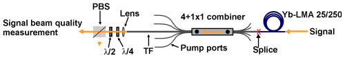
Fig. 14 Setup for beam quality measurements, TF: target fiber, PBS: polarization beam splitter.was used. A signal at a wavelength of 1064 nm was launched into the core of a 2.75 m long Ytterbium-doped DC fiber (Nufern YDF-25/250), which is specified with a signal core diameter of 25 µm (NA 0.06) and a pump core diameter of 250 µm (NA 0.46). Thus, the parameters of the passive TF of the combiner were matched to the active fiber. The coiling diameter of the active fiber was 12 cm to maintain near diffraction limited beam quality [20]. The transmitted signal had a power of about 200 mW and was propagating in reverse direction through the fiber combiner. The beam quality measurements were carried out with a Fabry-Perot ring-cavity. With this cavity it was possible to determine the power fraction in higher-order transversal cavity modes with respect to the Gaussian TEM00 mode by scanning the length of the ring-cavity over a free spectral range (FSR). A detailed description of the measuring setup can be found in Ref [21]. Due to the use of a polarization sensitive beam quality measurement, a half- and a quarter-wave retardation plate in conjunction with a polarization beam splitter (PBS) were used. The determined polarization extinction ratio was better than 17 dB after the propagation of the signal through the active fiber and the fiber combiner.

Before the fusion splice between the active fiber and the 4 + 1×1 combiner, the power in higher-order modes of the active fiber was determined. This measurement served as a reference beam quality for the active fiber. The mode scan in Fig. 15(a)

fiber combiner 2

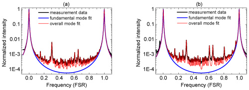
Fig. 15 Normalized transmitted intensity through a premode cleaner as a function of the ring-cavity length in units of a free spectral range for (a) the reference beam and (b) the signal feedthrough beam of a 4 + 1×1 fiber combiner.

shows the logarithmic normalized intensity over a free spectral range for the reference beam with a power in higher-order modes of 3.1%. This results in a fundamental fiber mode power of at least 96.9% for the reference beam. For the signal feedthrough of the fiber combiner, a power in higher-order modes of only 5.1% was found (Fig. 15(b)).

Consequently, the signal feedthrough fiber (0.7 m long TF) only led to an increase in power in higher-order transversal modes of maximal 2%. Furthermore, it must be considered that additional power transfer to higher-order transversal modes can also be caused by the fusion splice between the active DC fiber and the TF. Hence, good preservation of the signal beam quality, in conjunction with the low signal insertion loss of less than 3%, provides an excellent high power fiber component for monolithic fiber laser and amplifier systems.

Pump and signal combiner for bi-directional pumping of all-fiber lasers and amplifiers(2)

2. Optical design and relevant ray paths of the fiber combiner

A schematic side view of the side-pump combiner consisting of a pump feeding fiber (PFF), a coreless intermediate fiber (IF) and a target fiber (TF) is shown in Fig. 1

high-power-isolator-1064nm

Fig. 1 Schematic side view of a side-pumped double-clad fiber including important ray paths.

. The diameter of the PFF core and the cladding was 105 and 125 µm, respectively. The NA of the pure silica PFF core used in the simulations was 0.15, 0.22 or 0.3 and, therefore, the refractive index of the PFF cladding was depressed in comparison to the refractive index of the PFF core. The cladding of the PFF was surrounded by a polymer coating only for mechanical protection of the fiber. Therefore, the PFF preserved the same waveguide properties after removal of the polymer coating. In the case of side-pumping without an IF, the higher refractive index of the core of the PFF would suppress the pump power transfer into the TF as long as the PFF is untapered. An increase of the NA of the pump light due to tapering of the PFF would result in an increase of the pump power transfer, though only for rays that exceed the NA of the PFF core. Thus, it is especially difficult to couple pump light rays with a low NA into the TF. Unfortunately, this type of PFF is typically used as high power delivery fiber of pump diodes. To overcome this problem, without removing the glass cladding of the PFF, a coreless IF was inserted in the fiber combiner setup. At first the ~30 cm long IF with a cladding diameter of 125 µm was fusion spliced to the PFF. The IF had a NA of 0.46 due to the refractive index difference (Δn) between fused coupler silica and the outermost polymer coating. After removing the polymer coating (e.g. with acetone) along a certain section of the IF (~15 mm), the IF was individually tapered, and afterwards the converging taper portion was laterally fused with the TF. The fusion level (FL) is defined as FL=(2z)/(dIF+dTF), where dIF and dTF are the cladding diameters of the IF and the TF at a certain taper position, respectively, and z represents the distance of the fused IF and TF, as depicted in Fig. 1. The FL was experimentally determined by measuring dIF, dTF and z at different positions along the converging taper portion with an optical microscope. With this measurement an averaged very low FL of 1.99 was determined, which was also used for the simulations. The overlap area between the TF and the IF is defined as the fusion zone. In contrast to the converging taper portion, the diverging taper portion of the IF was not fused to the TF, but placed under a small angle to the fiber axis of the TF, resulting in a small air gap between the IF and the TF. The employed TF was a DC fiber with a core diameter of 25 µm (NA 0.06) and a cladding diameter of 250 µm (NA 0.46). The cladding of the TF was also surrounded by a polymer coating, except along the coupling region of the combiner. The low index coating had to match the mechanical and additionally the optical properties of the DC fiber. An anchoring bond was used to fix the fiber bundle on each side on a copper substrate. Figure 1 shows the anchoring bond only on the right-hand side without the copper substrate. Additionally, the anchoring bond served as a pump light stripper for rays which do not satisfy the NA criterion of the TF.

Before proceeding with a more detailed investigation with the aid of simulations in the next section, we will qualitatively discuss some important ray paths of the fiber combiner. Pump light rays guided into the PFF and entering the tapered portion of the IF increase in NA as long as the rays propagate along the converging taper. As a rule of thumb, the pump light input NA increases by a factor of the taper ratio (TR), which is defined as the ratio of the original fiber diameter to the diameter of the taper waist. Pump light coupling into the TF occurs as soon the rays enter the fusion zone. The converging taper portion increases the probability for pump light transfer into the TF, since the number of ray-bounces along the lateral surface of the IF increases. Particularly, pump light rays with a low input NA couple more efficiently due to the converging taper.

Pump light rays remaining in the IF, and consequently not coupling into the TF, can occur as transmitted power (TP: transmittedpower, Fig. 1) or power leakage into the ambient air (PAA: power leakage into the ambient air, Fig. 1). As long as the condition for internal total reflection is satisfied, the pump light rays are detected as TP, otherwise the rays escape into the ambient air as PAA. The angle of total internal reflection for the uncoated IF is 43.6°, since Δn between fused silica and air is 0.45 at a wavelength of 976nm pump laser protector, which means the IF can guide light up to a theoretical NA of 1.05. Of course, the NA cannot exceed 1.0. Therefore, pump light rays with a theoretical NA in the range of more than 1.0 up to 1.05 would experience total reflection in the case of an existing fiber endface. Pump light rays which exceed the theoretical NA of 1.05 occur as PAA.

For almost loss-free pump light coupling into the TF it is necessary that the rays enter the TF before they exceed the cladding NA of the TF of 0.46. This desired coupling behavior can usually be achieved by adapting the taper parameters. However, pump light coupling for rays with an NA far above 0.46 cannot be completely suppressed. Unfortunately, this pump power leakage couple into the coating of the TF (PCT: power leakage into the coating of the target fiber) and can damage it.

In summary, the input pump combiner will be divided into the coupled pump power and the losses including PAA, PCT and TP (Fig. 1).

Pump and signal combiner for bi-directional pumping of all-fiber lasers and amplifiers(1)

Abstract

We developed an all-fiber component with a signal feedthrough capable of combining up to 6 fiber-coupled multi-mode pump sources to a maximum pump power of 400 W at efficiencies in the range of 89 to 95%, providing the possibility of transmitting a high power signal in forward and in reverse direction. Hence, the fiber pump combiner can be implemented in almost any fiber laser or amplifier architecture. The complete optical design of the combiner was developed based on ray tracing simulations and confirmed by experimental results.

(N+1)X1 Pump and Signal Combiner

1. Introduction

For the realization of compact, reliable, rugged and efficient monolithic high power fiber laser systems, the efforts of integrating all-fiber components have been increased in recent years [1,2]. A key component of a highly integrated fiber laser or amplifier system is a high power all-fiber signal and pump combiner.

The most common type of fiber combiner, a fused tapered fiber bundle (TFB) [3,4], is based on the fiber end face pumping technique and is probably the most sophisticated pump combiner capable of handling several hundred watts of pump power [5]. A TFB with signal feedthrough consists of a central input signal fiber, guiding the signal light, surrounded by several multi-mode fibers, guiding the pump light, and an output pigtail double-clad (DC) fiber which combines the signal and pump light in a single pigtail fiber. In order to match the diameter of the fiber bundle to the diameter of the output pigtail fiber, the bundle is slowly melted and tapered. After the tapering process the fiber bundle is cleaved around the taper waist and fusion spliced to the output pigtail DC fiber. However, tapering of the fiber bundle inherently involves increasing the numerical aperture (NA) of the pump light and a change of the mode field diameter (MFD) of the signal light. Hence, the necessary optical matching and mechanical alignment requirements between the tapered fiber bundle and the output pigtail DC fiber can lead to several drawbacks of the TFB structure: (1) less flexibility in the choice of input fibers that match the output pigtail DC fiber after the tapering process, (2) a slight mismatch or misalignment between the signal mode field diameters (MFD) of the tapered input signal fiber and the output pigtail DC fiber leads to a degradation of the beam quality, primarily in conjunction with signal insertion loss, and (3) in the case of a backward propagating signal, e.g. for a counter-propagation pumped fiber amplifier, the signal insertion loss (up to 10%) can cause damage to the pump diodes due to their insufficient isolation against amplified signal light.

A more promising approach to overcome these problems is side-pumping technology, which involves coupling the pump light via the outermost cladding surface into the fiber. The key advantage of this technology is the uninterrupted signal core, eliminating the need for an additional fusion splice in conjunction with signal mode matching. In recent years several proposals for side-pumping of DC fibers have been reported, such as V-groove side pumping [6], a mirror embedded in the inner cladding of a DC fiber [7] or side-coupling by an angle polished pump fiber [8]. However, for most of these side-pumping configurations it is difficult to reach the mechanical accuracy required for a stable and efficient pump light coupling.

A more rugged approach is a monolithic all-fiber combiner like the GT-Wave coupler [9], the employment of a tapered capillary around a multi-clad fiber [1011] or direct fusion of one or more tapered multi-mode fibers to the outermost cladding of multi-clad fibers [1214]. In Ref [11] seven pump delivery fibers with a core diameter of 110 µm (NA 0.22) were combined and laterally coupled via a tapered capillary into a DC fiber with a core diameter of 400 µm (NA 0.46), which led to a combined pump power of 86 W with a coupling efficiency of ~80%. In Ref [13], direct lateral fusion of one tapered pump delivery fiber with a core diameter of 200 µm (NA 0.46) to a DC fiber of 250 µm (NA 0.46) led to a coupling efficiency of 90% at a pump input power of 120 W, furthermore, a pump delivery fiber with a diameter of 400 µm (NA 0.46) was used to couple a pump power of 300 W with an efficiency of 85% into a DC fiber with a diameter of 400 µm (NA 0.46). These impressive coupling efficiencies for one pump port were achieved by use of a straight and a tapered fiber section, allowing for highly efficient coupling of pump light rays with a high numerical aperture. Thus, in Ref [13] the impact of the straight fiber section on the side-pump coupling process was discussed. However, a review of the literature reveals that the impact of the fiber and taper parameters on the pump coupling behavior as well as the loss mechanism have not yet been investigated in detail for side-pumped combiners based on direct fusion of one or several tapered multi-mode fibers to the outermost cladding of a DC fiber.

We report detailed simulations and experiments for a component which combines up to 6 multi-mode fibers with a core diameter of 105 µm (NA 0.15 or 0.22) into a DC fiber with a cladding diameter of 250 µm (NA 0.46) via side-coupling. Firstly, we explain the principle of the optical design of the fiber combiner. For a fiber combiner with a single pump port, the achievable pump coupling efficiency and the corresponding loss mechanisms were investigated. For multiple pump ports, the simulations and experiments showed that with each additional pump port, the taper parameters need to be adjusted in comparison to a single pump port configuration. These simulation results can also be used as an estimation for fiber combiners, which combine one or several multi-mode fibers with a core diameter of 200 µm (NA 0.22) into a DC fiber with a cladding diameter of 400 µm (NA 0.46). Therefore, this work covers two important fiber combiner types, since active fibers with cladding diameters of 250 or 400 µm are typical sizes provided by fiber manufacturers and used for continuous wave and pulsed laser systems. In addition, we also investigated the signal feedthrough of the combiner. We demonstrated a low signal insertion loss, maintenance of an excellent signal beam quality and an efficient isolation of the pump diodes against signal light in the case of a reverse propagating signal. The preservation of the signal light properties by the fiber combiner was utilized in Ref [15] for the realization of a counter-propagation pumped single-frequency fiber amplifier with an amplified signal power of 300 W.