Channel CWDM Mux & DeMux – Features and Applications

The CWDM are by and large in view of thin coat channel innovation which is the type of item fall under the WDM class. There arrived in a total scope of Class-8 CWDM Mux-Demux and also OADM that stands for Optical Add Drop Multiplexer units with a specific end goal to meet a wide range of necessities and system arrangements.

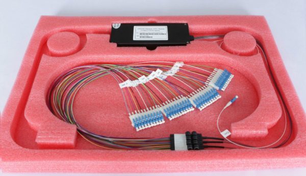
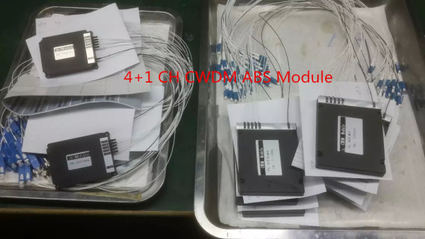
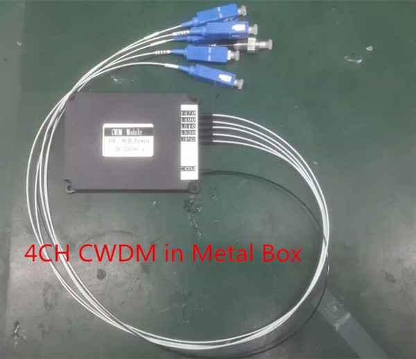
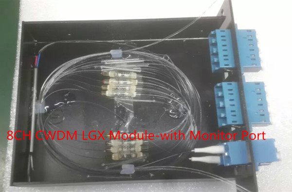
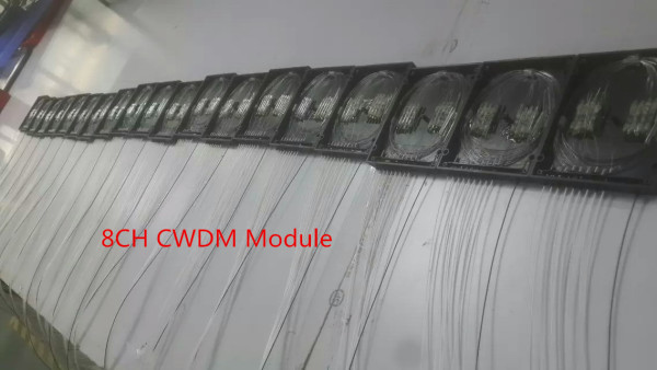
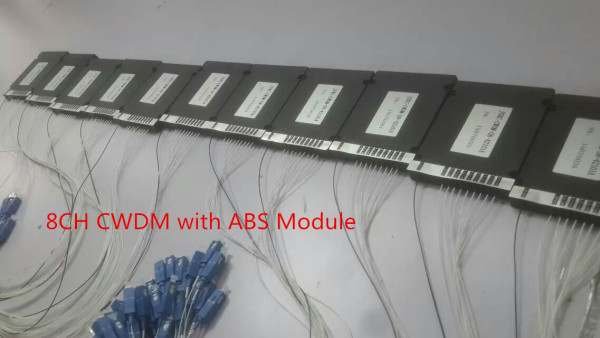
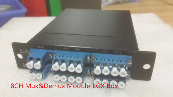
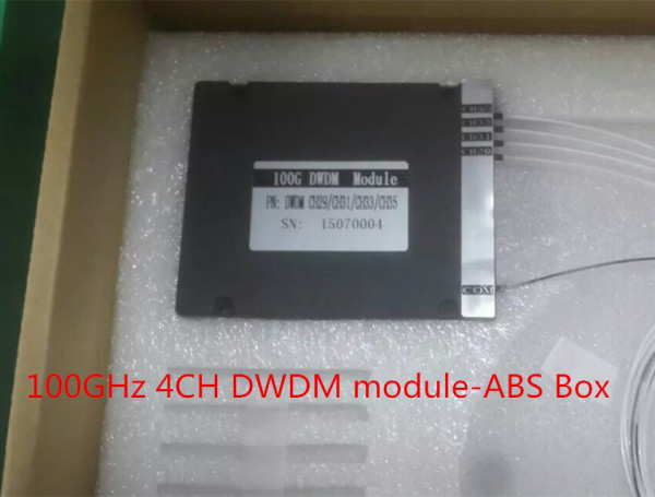
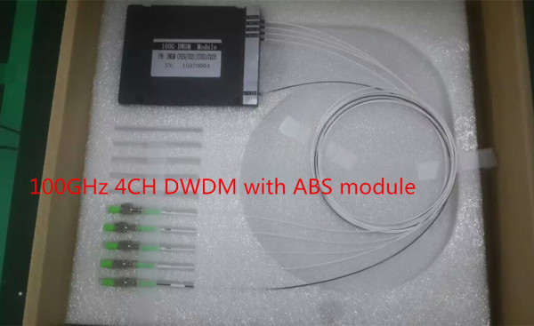
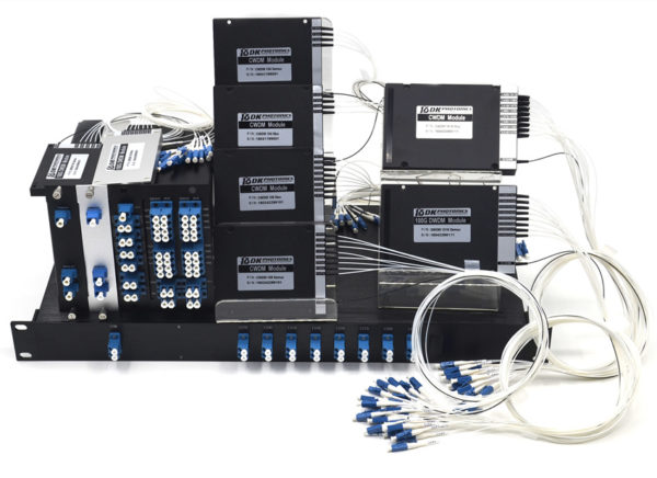
Likewise, it has across the board applications that require the Channel CWDM. Some of them include: Gigabit and 10G Ethernet, Fiber Channel, ATM, ESCON, in Metro total, SDH/SONET, and CATV and so forth. Presently, we should talk about the accompanying components and utilizations of Channel CWDM that settle on it an ideal decision for all. The CWDM Mux / Demux items give up to 16-channel or even 18-channel Multiplexing on a solitary fiber. Standard CWDM Mux/Demux bundle sort include: ABS box bundle, LGX pakcage and 19″ 1U rackmount.

Highlights

  • The loss of insertion quality creates from the presentation of a gadget into the optical fiber is by and large lesser in CWDM than alternate gadgets; this produces short inclusion costs.
  • Channel-8 CWDM is dependably very steady and solid in the meantime. Not at all like every other sort of WDM class, the Channel CWDM has higher dependability.
  • The CWDM items are typically Epoxy free on optical way; this prompts better working and Epoxy free condition while the execution.
  • In CWDM, the channel segregation is very high. This expanded seclusion prompts better and successful outcomes.

Applications

WDM and Access Organize: As these channel sorts are the piece of WDM class, these have their best application in the WDM and also Access systems.

Line Observing: These items have their incredible use in line checking. This guarantees there is no crash on a similar line of some other range or frequency.

Cellular Application: The CWDM channel arrangements have their utilizations and applications additionally in the Cellular area, and advances as the unequaled panacea for some different parts and ventures.

Telecommunication: The broadcast communications devours Channel-8 CWDM at an incredible rate. It needs to utilize these items for the straightforward transmission of signs and utilization of the filaments for the same.

Aside from every one of the elements and applications, the capacity of CWDM is additionally to unravel the deficiency of fiber and straightforward transmission of exchange while lessening the charges of system building. This is the motivation behind why the Channel CWDM and LGX CWDM Mux and DeMux Module have a matter of extraordinary heights in the realm of fiber optics, flag transmission and multiplexing and so forth.

Get Acquainted With Athermal AWG DWDM Module & its Astounding Applications

The element of a succession of high performance products that are based on the technology called silica-on-silicon planar and an exclusive athermal packaging design demanding zero software, electrical power, or temperature control for an entirely passive DWDM solution are referred to as Athermal Arrayed Waveguide Grating Dense Wavelength Division Mux/Demultiplexer which is also known as Athermal AWG DWDM Modules.

Athermal AWG DWDM Module

This range of modular products delivers an amalgamation of high channel isolation and very low loss along with longevity as well as reliability. Each module in the range is capable of performing Mux and Demux functions. With Flat top spectral response, both band devices are easily available (including L- and C- band). Apart from this, the custom frequency grids, connectorisation options and fiber type solution are also available. These functions make the modules ideal for several applications; some of them are discussed below:

Astounding Applications of an Athermal AWG DWDM Module:

  • WDM transmission: The WDM transmission is the process of transferring WDM, (the acronym for Wavelength Division Multiplexing) which is a method of combining multiple signals onlaser beams at different IRs (infrared wavelengths) –along the fiber optic media. With 100GHz Athermal AWG DWDM Module, the WDM transmission process becomes easy and effectual.
  • WDM based ADM: As Add / Drop Multiplexing is a multiplexing function that is employed in optical technology but can also be used in electric signal transmissions by using the principle of WDM transmission.
  • Metro and long haul networks: Metro networks and also long haul networks need to use Athermal AWG DWDM Module on wide basis. These modules offer the long haul networks with the ability to mail information, post news on bulletin boards, and logon at a remote site etc.
  • Optical Signal Processing: An Optical Signal Processing, shortened to OSP is the technology (process) that enables the processing of ocular signals in a way that the data content of such signals may be modified without converting the signals into the electrical domain. This whole process too requires 100GHz Athermal AWG DWDM Module for its efficient yet effective working.

Beyond all the listed applications of Athermal AWG DWDM, there are some more, one of which is ‘Wavelength selective routing’. The AWG DWDM is an ideal choice for all the mentioned applications because of its fetching features which encompass 100GHz ITU channel spacing, Low insertion loss, high stability and reliability etc. These features make the modules effective, durable and long term reliable.

Field-Terminated Fusion Splice-On Connector-North American Market Forecast

According to ElectroniCast, the quantity of field-terminated fiber optic splice-on connectors in North America will increase at an explosive annual rate of 41.9% …

ElectroniCast Consultants, a leading market research & technology forecast consultancy addressing the fiber optics communications industry, today announced the release of a new market forecast of the consumption of field terminated fiber optic fusion splice-on connectors in North America.

Fusion_Splice_on_Connector

Field terminated fiber optic fusion Splice On Connectors (SOC) are installed for rapid repairs or for limited space situations where pre-terminated fiber cabling may be difficult, such as when the cable assembly needs to pass through small openings such as conduit.  The splice-on connectors are an option when the precise length of the optical fiber link is not pre-determined and a field-installed termination solution is required, such as in Fiber to the Home (FTTH) and other communication applications.

Last year, 306-thousand field-terminated fiber optic fusion splice-on connectors were installed in non-OEM applications in North America.  The number of connectors is forecast to increase at an explosive rate of 41.9% per year, reaching 2.49 million units in 2020.  Market forecast data in this study report refers to consumption (use) for a particular calendar year; therefore, this data is not cumulative data.

The Telecommunications application category is forecast to maintain the leadership in relative market share through the year 2018, until the Premises Networks application category is set to capture the lead.  Telecommunication use is forecast for 35.5% annual growth in quantity (2014-2020), mainly driven by access optical fiber deployment.  The Cable TV application is also driven by the use of connectors for FTTH (Home) and FTTB (Building/MDUs – Multiple Dwelling Units).

The market forecast segments the connectors by single-mode and multimode optical fiber, as well as into the following types: MPO, LC, FC, ST, SC, and other.  The use of single mode fiber optic field-terminated fusion splice-on connectors in North America is forecast to increase from 173.8-thousand units in 2014 to 1.49 million in 2020.  Multimode fiber is best suited for use in short lengths, such as those used in datacom and specialty networks and in 2020, multimode connectors are expected to reach 1-million units.

“In 2014 in North America, 4.3-thousand new fusion splicers were brought into Premises Datacom, and the use of field terminated fusion splice on connectors is a major market driver for the use of fiber optic fusion splicers used in premises network applications, the data center (DC) and longer link length datacom cable installations,” said Stephen Montgomery, Director of the ElectroniCast market study.

“The SOCs are emerging as a viable alternative to pre-terminated fiber optic cables (pigtail and cable assemblies/ patch cords).  Also, based on primary research interviews with network planners and installers, we are finding that field terminated fusion splice-on connectors are rapidly being accepted as a go-to solution.  With SOCs, communication network technicians can install reliable cable links with exact lengths, eliminating cable shortness or excess slack that is typically a result with the pre-terminated cable solution,” Montgomery added.

Tags: CWDM Multiplexer, DWDM Multiplexer,19″ rack mount chassis CWDM, ABS plastic box, CWDM MUX/DEMUX Module,  LGX CWDM Module,8CH CWDM Module, 16CH CWDM Module

The Modern Data Center – Modular Data Center

The modern data center is a complex place. The proliferation of mobile devices, like tablets and smartphones, place an ever-increasing pressure on the IT departments and data centers. End-user and customers’ expectation levels have never been higher and the demand for data shows no sign of slowing down. Data center managers must manage all of these elements while also remaining efficient and keeping costs under control. So where does the data center go from here?Modular Data Center

One thing I have noticed in the evolution of the modern data center is that the facilities are gaining importance; improving energy efficiency and IT management have come to the forefront. Maximizing the organization’s resources is vital, and that means delivering more to facilities and equipment without expending more on staffing. IDC forecasts that during the next two years, 25 percent of all large and mid-sized businesses will address the power and cooling facility mismatches in their data centers with new IT systems and put a 75 percent cap on data center space used. So there again is the crucial challenge of doing more and innovating while keeping budgets and spend under control.

Another key part of the next generation data center mix is automation. Today’s data center manager is engaged in sourcing the right automation tools that will help them manage energy consumption and add new technology without disrupting normal operations. These are a few of the key challenges in the modern data center—so data center managers and IT departments must find ways to address them.

Where does the Data Center Go Next?

At the heart of data center evolution is the information technology sector’s rapid rate of change. Many new products and services must be implemented with much less time to value, and data centers need to be agile enough to assess and accommodate them all. If you examine enterprise data centers, then you might observe the ways that cloud computing and hyperscale innovations are displacing traditional enterprise systems, with new paradigms pioneered by innovators like Amazon and Google. With new options being developed, enterprises now have to chart strategies for cloud computing, including public, private or hybrid cloud. Gauging where the technology will go next is difficult to tell. Will the traditional vendors, such as Cisco and EMC, prevail or will new paradigms from Nutanix or Simplivity disrupt and displace these traditional data center dominators?

The race is on to manage the rapid rate of change while also staying agile, meeting end-user expectations and managing costs. For example, data center managers must handle the level of capacity their data center requires while ensuring they don’t overspend on unused capacity. This is where the focus on data center design comes into play.

Taking the Data Center Forward

These specific needs and challenges that the modern data center faces require working with the right tools and solutions. Modular, purpose-built data center infrastructure allows organizations to develop data center services based on need—when capacity rises and where capacity is needed. For example, we’ve observed in Singapore that most data centers operate slightly above 2.1 Power Usage Effectiveness (PUE). This means that companies spend more on cooling their data center rather than on operating and powering the IT equipment. It is a simple challenge—drive efficiency without impacting operations. You want to drive PUE down to approximately 1.06, regardless of where you need to operate, and reap huge energy savings while better serving customers. If done right, there is a positive environmental impact.

Changing the paradigm of the traditional data center enables organizations to reap these rewards. Assessing and establishing business objectives that reflect what is possible, rather than what always has been or what is easier and more comfortable, has led to innovative services and new business models that reset the competitive standards for everyone. Better PUE is a mandatory step in this process. The PUE journey continues as evidenced by Amazon, which had recently taken to harnessing wind to power its data centers. Modular data centers will play a major part in this PUE journey, thanks to more efficient use of energy and greater flexible support for resiliency and compute density.

How much do you know about CWDM Multiplexer and DWDM Multiplexer

CWDM multiplexer and DWDM multiplexer are two main products of WDM multiplexer. The full name of WDM, CWDM and DWDM are wavelength division multiplexing, coarse wavelength division multiplexing and dense wavelength multiplexing respectively. How much do you know about them? If you have no idea, the following introduction will help you a lot.

In the very first place, let’s get to know what the WDM is. Based on a single fiber optic transmission, many optical signals that are loaded with information and have different wavelengths can be synthesized into one single beam by WDM multiplexer. Then, a special communication technology will be adopted to separate those optical signals at the receiving terminal. On the basis of WDM technique, the CWDM device and DWDM device are two popular products in the current market.

CWDM device

When it comes to the CWDM multiplexer, first of all, it provides service for metropolitan area network access layer, whose working principle is in line with WDM multiplexer. However, it simplifies the structure largely. For example, the filter film layer number of CWDM is just 50, while the WDM is as many as 200 layers. That is to say, the rate of finished products has been improved and the cost has been reduced largely. Besides low cost, the CWDM device is also advantageous in small volume, small power consumption, convenient maintenance and large transmission capacity. The laser device in the system doesn’t need semiconductor refrigerator and temperature controller, which can lessen the power consumption obviously. However, the CWDM also has shortcomings. For instance, developing and simplifying the optical transceiver module and optical component is urgent to be solved.

DWDM device

As to the DWDM multiplexer, comparatively speaking, it makes the best use of fiber-optical bandwidth and enhances the message capacity of cellular system, which is well-known for simple dilatation and stable performance. Integrated system and open system are two dominant application systems of DWDM multiplexer, which are based on different wavelength conversion technologies. No matter which system is adopted, the free-running 1510nm wavelength will be chosen to carry OSC or optical supervisory channel so as to transmit information. Such an OSC is a comparatively independent subsystem, which offers maintenance and management information.

The last question is what advantages WDM technique has when compared with traditional transmission methods. Generally speaking, it includes such aspects as making best use of low-loss wave band, transmitting several optical signals in one optical fiber, good flexibility, low investment cost, excellent system reliability and fast and convenient recovery.


Tags: CWDM Multiplexer, DWDM Multiplexer,19″ rack mount chassis CWDM, ABS plastic box, CWDM MUX/DEMUX Module,  LGX CWDM Module,8CH CWDM Module, 16CH CWDM Module

Do you know these about CWDM Multiplexer and DWDM Multiplexer?

Do you know these about CWDM Multiplexer and DWDM Multiplexer?

Wavelength division multiplexing (WDM) is a technology or technique modulating numerous data streams, i.e. optical carrier signals of varying wavelengths (colors) of laser light, onto a single optical fiber. The goal of WDM is to have a signal not to interfere with each other. It is usually used to make data transmission more efficiently. It has also been proven more cost effective in many applications, such as WDM network applications, broadband network application and fiber to the home (FTTH) applications and so on. According to channel spacing between neighbored wavelengths, there are two main types of WDM, including Coarse WDM (CWDM) and Dense WDM (DWDM). Though both of them belong to WDM technology, they are quite different. Then, what are the differences between them? This paper will give you the answer.

Definition of CWDM

CWDM is a method of combining multiple signals on laser beams at various wavelengths for transmission along fiber optic cables, such that the number of channels is fewer than in DWDM but more than in standard WDM. “Course” means the channel spacing is 20nm with a working channel passband of +/-6.5nm from the wavelengths center. From 1270nm to 1610nm, there are 18 individual wavelengths separated by 20nm spacing.

Definition of DWDM

DWDM is a technology that puts data from different sources together on an optical fiber, with each signal carried at the same time on its own separate light wavelength. “Dense” refers to the very narrow channel spacing measured in Gigahertz (GHz) as opposed to nanometer (nm). DWDM typically uses channel spacing of 100GHz with a working channel passband of +/-12.5GHz from the wavelengths center. It uses 200GHz spacing essentially skipping every other channel in the DWDM grid. And it has also gone one step further using an Optical Interleaver to get down to 50GHz spacing doubling the channels’ capacity from 100GHz spacing.

CWDM vs DWDM

According to the content above, you will find some small differences between them. 16CH CWDM Module is defined by wavelengths and has wide range channel spacing. DWDM is defined by frequencies and has narrow channel spacing. What’s more, what other differences do they have?

Capacity of Data

In fiber optic network system, DWDM system could fit more than 40 different data streams in the same amount of fiber used for two data streams in a CWDM system. In some cases, CWDM system can perform many of the same tasks compared to DWDM. Despite the lower transmission of data through a CWDM system, these are still viable options for fiber optic data transmission.

Cost of Cable

CWDM system carries less data, but the cabling used to run them is less expensive and less complex. A DWDM system has much denser cabling and can carry a significantly larger amount of data, but it can be cost prohibitive, especially where there is necessary to have a large amount of cabling in an application.

Long-haul or Short-haul Transmission

DWDM system is used for a longer haul transmission through keeping the wavelengths tightly packed. It can transmit more data over a significantly larger run of cable with less interference. However, CWDM system cannot travel long distances because the wavelengths are not amplified, and therefore CWDM is limited in its functionality over longer distances. If we neeed to transmit the data over a very long range, DWDM system solution may be the best choice in terms of functionality of the data transmission as well as the lessened interference over the longer distances that the wavelengths must travel. As far as cost is concerned, when required to provide signal amplification about 100 miles (160km), CWDM system is the best solution for short runs.

According to the content above, maybe you have already understood some differences between CWDM and DWDM by the comparision of them from definition, capacity, cable cost and transmission distance etc. And here is also a figure of comparisons between CWDM and DWDM which may help you to consolidate your understanding of this paper.

CWDM Multiplexer and DWDM Multiplexer

Tags: 19″ rack mount chassis CWDM, ABS plastic box, CWDM MUX/DEMUX Module,  LGX CWDM Module,8CH CWDM Module, 16CH CWDM Module

2~18CH CWDM MUX/DEMUX Module from DK Photonics

The key components in a WDM system are the optical wavelength multiplexer (MUX), and the de-multiplexer (DEMUX). In general, a CWDM (coarse WDM) MUX/DEMUX deals with small numbers of wavelengths, typically eight, but with large spans between wavelengths (spaced typically at around 20nm). A DWDM (dense WDM) MUX/DEMUX deals with narrower wavelength spans (as small as 0.8nm, 0.4nm or even 0.2nm), and can accommodate 40, 80, or even 160 wavelengths.

The one kind of DK Photonics LGX CWDM MUX/DEMUX modules are bi-directional passive optical multiplexers and de-multiplexers, allowing multiple optical signals at different wavelengths to pass through a single optical fiber strand.

simplex-bidi-transmission-cwdm-mux-demux

The second DK Photonics ABS CWDM MUX/DEMUX modules are duplex fiber link bi-directional multiplexers and de-multiplexers, allowing multiple optical signals’ at different wavelengths to pass through duplex optical fiber.

duplex-bidi-transmission-cwdm-mux-demux

The last one kind is simplex directional CWDM MUX only or CWDM DEMUX only. The kind of mux and demux must be used with each other.

simplex-directional-transmission-cwdm-mux-demux

CWDM MUX/DEMUX solution lets operators make full use of available fiber bandwidth in local loop and enterprise architectures. Our CWDM MUX/DEMUX modules split up to 18 channels (20 nm spaced) to a single fiber. The standard packages are ABS Plastic Box, 19″ Rack Mount Chassis CWDM Mux/Demux  and LGX Metal Box Mux/Demux. No matter what kinds of connectors (such as FC, ST, SC, LC, etc.) are all available and we can also mix connectors on one device.

CWDM MUX+DEMUX 8 Channels (Dual Fiber) Module

DK Photonics offers a wide range of WDM (Wavelength Division Multiplexing) optical networking products that allow transport of any mix of services from 2Mbps up to 100Gbe over dark fiber and WDM networks providing for the entire set of the most demanding CWDM and DWDM network infrastructure needs.

Ovum: Optical components market to grow 8% in 2014 from $6.8 bn in 2013

The global optical components (OC) market is expected to grow 8 percent in 2014 from $6.8 billion in 2013, said Ovum.

In 2013, the OC market increased 3 percent from 2012. Ovum said main growth drivers in 2013 were data communication sales driven by large data centers, 100G coherent demand, and unexpected growth in sales of transceivers for fiber-to-the-antenna applications for 4G build-outs.

“Demand for 100G metro–optimized transmission gear will begin shipments and ramp in 2015. Multiple component vendors introduced components and pluggable optics for 100GHz DWDM in anticipation. Opportunities are also emerging in the data center for high-speed interconnects,” said Daryl Inniss, practice leader for Telecoms Components at Ovum.

In the first quarter of 2014, the optical components market declined 1 percent sequentially and grew 7 percent compared to the year-ago period.  New lower telecom prices were one of the main reasons for the marginal growth in OC on quarter-on-quarter basis.

Ovm said demand for 100G components for coherent transmission in WAN, datacom transceivers at 10 and 40G, and fiber-to-the-antenna transceivers is expected to continue. Traffic continues to increase, and high-speed optics being used in new applications are helping to drive the market forward.

Global-optical-components-market-forecast

The WAN OC segment, which includes components in telecom carriers’ core and metro networks, the largest segment, will grow at a compound annual growth rate (CAGR) of 11 percent to $7 billion in 2019. Demand for 100G components and modules is a big driver for growth in WAN.  Ovum expects strong demand for pluggable coherent transceivers in 2015.

Datacom will be expanding at a 16 percent CAGR to reach $4.2 billion in 2019 — led by demand for 10 and 40G components in the early years and then 100G in the later years driven by the availability of server ports supporting data rates greater than 10G.

Access — including CATV, FTTx and transceivers for the fiber-to-the-antenna application — will decline at 2 percent CAGR to $1.1 billion in 2019. The decline will be driven by the FTTx application, where volumes are nearly constant through the forecast period but price declines are projected to pull down revenues.


DK Photonicswww.dkphotonics.com  specializes in designing and manufacturing of high quality optical passive components mainly for telecommunication, fiber sensor and fiber laser applications,such as PLC Splitter, WDM, FWDM, CWDM, DWDM, OADM,Optical Circulator, Isolator, PM Circulator, PM Isolator, Fused Coupler, Fused WDM, Collimator, Optical Switch and Polarization Maintaining Components, Pump Combiner, High power isolator, Patch Cord and all kinds of connectors.

Comparation Between EPON and GPON

With the continuous progress of science and technology, the Internet has gradually gone into the homes of the ordinary people, and the speed of broadband has increasingly become the topic of people in the entertainment and work often, from narrowband dial-up to broadband Internet, and then the fiber access Internet, broadband network, the rapid pace of PON technology gradually come to the front. Currently, there are two quite compelling PON standard has been officially released, which are GPON standard developed by the ITU / FSAN and EPON standard developed by IEEE 802.3ah working group. PON technology has been no doubt the ultimate solution for the future FTTH era. EPON and GPON who will the dominant FTTH tide has become a new hot debate. What’s the difference between EPON and GPON?

GPON and EPON Differences

Perhaps the most dramatic distinction between the two protocols is a marked difference in architectural approach. GPON provides three Layer 2 networks: ATM for voice, Ethernet for data, and proprietary encapsulation for voice. EPON, on the other hand, employs a single Layer 2 network that uses IP to carry data, voice, and video.

A multiprotocol transport solution supports the GPON structure (Figure 1). Using ATM technology, virtual circuits are provisioned for different types of services sent from a central office location primarily to business end users. This type of transport provides high-quality service, but involves significant overhead because virtual circuits need to be provisioned for each type of service. Additionally, GPON equipment requires multiple protocol conversions, segmentation and reassembly (SAR), virtual channel (VC) termination and point-to-point protocol (PPP).

Figure 1: Diagram showing a typical GPON network.

EPON provides seamless connectivity for any type of IP-based or other “packetized” “communications” (Figure 2). Since Ethernet devices are ubiquitous from the home network all the way through to regional, national and worldwide backbone networks, implementation of EPONs can be highly cost-effective. Furthermore, based on continuing advances in the transfer rate of Ethernet-based transport — now up to 10 Gigabit Ethernet — EPON service levels for customers are scalable from T1 (1.5 Mbit/s) up through 1 Gbit/s.

Figure 2: Diagram showing a typical EPON network.

Upstream Bandwidth

Subtracting the various system run overhead from the total bandwidth of the system uplink transmission is the upstream available bandwidth. It has a great relationship with the number of the ONU contained in the system, DBA (Dynamic Bandwidth Allocation) algorithm polling cycle, the type of bearer services, as well as the various business proportion. EPON and GPON are broadband access technology, hosted business IP data services. Below we will calculate the uplink the beared pure IP services available bandwidth of EPON and GPON that contain 32 ONUs, fiber optic coupler,the case of polling period 750s.

EPON

EPON upstream rate is 1.25 Gbit/s. Because the 8B/10B line coding, each 10bit are 8bit valid data, so its effective upstream transmission bandwidth is 1 Gbit/s. EPON upstream overhead of running the system and its proportion of the total bandwidth are as following:

1. Used for the the burst reception of physical layer overhead: about 3.5%;

2. Ethernet frame encapsulation overhead: about 7.4%;

3. MPCP (Multi-Point Control Protocol) and OAM operation and management of maintenance protocol overhead: about 2.9%;

4. DBA algorithm resulting in the remaining time slots (that is not sufficient to transfer a complete Ethernet frame time slot) wasted: about 0.6%;

5. EPON upstream total overhead is all of the above about 144 Mbit/s, the available bandwidth is about 856 Mbit/s.

GPON

GPON supports a variety of rate levels, has asymmetric rate that downlink is 2.5Gbps or 1.25Gbps, the upgoing is 1.25Gbps or 622 Mbps. NRZ encoding the uplink total bandwidth for 1.244 Gbit/s, GPON upstream overhead of running the system as following:

1. The proportion of its total bandwidth is used for the the burst reception of physical layer overhead: about 2.0%;

2. GEM (GPON encapsulation method) frame and the Ethernet frame encapsulation overhead: about 5.8%;

3. The PLOAM (physical layer operation, management and maintenance) protocol overhead: about 2.1%;

4. Remaining slots of the DBA algorithm introduced the additional encapsulation overhead: about 0.8%.

5. GPON upstream total overhead is all of the above about 133 Mbit/s, the available bandwidth about 1111 Mbit/s.