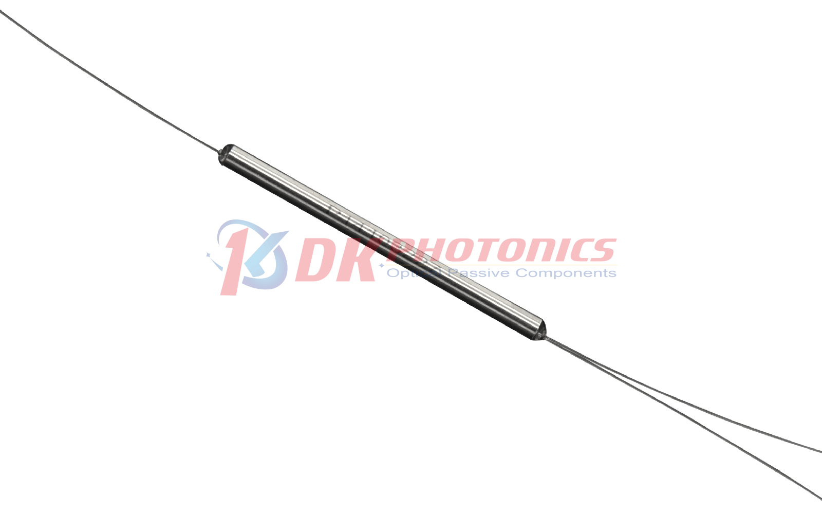
DK Photonics uses unique fusing technique and polarization maintaining fiber to build the 980/1030nm polarization maintaining fused WDM. It features low excess loss, small size and high polarization extinction ratio. PM fused WDM is widely used for fiber laser, optical sensors and optical gyro. This product can also be used to multiplex other wavelengths. Including 980/1030 nm (pulsed laser applications) and 1064/1550 nm (Erbium-Ytterbium pumping).
DK Photonics uses unique fusing technique and polarization maintaining fiber to build the 980/1030nm polarization maintaining fused WDM. It features low excess loss, small size and high polarization extinction ratio. PM fused WDM is widely used for fiber laser, optical sensors and optical gyro.
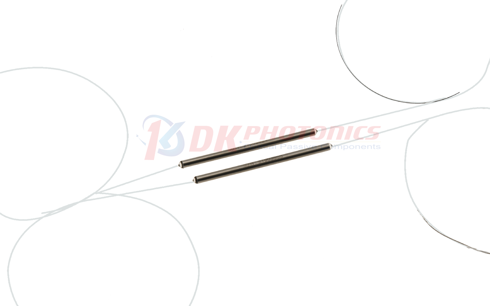
This product can also be used to multiplex other wavelengths. Including 980/1030 nm (pulsed laser applications) and 1064/1550 nm (Erbium-Ytterbium pumping). Low power (300mW, 500mW) and high power (20W) handling are available. They are ideal for polarization maintaining fiber amplifiers, fiber lasers, and high-speed communication system and instrumentation applications.
|
Parameter |
Unit |
Specifications |
|
|
Operating Wavelength |
nm |
980/1030 |
|
|
Operating bandwidth |
nm |
±5 |
|
|
Max. Insertion Loss |
Shorter wavelength |
dB |
0.60 |
|
Signal Port |
dB |
0.60 |
|
|
Min. Isolation |
dB |
13 |
|
|
Min. Extinction Ratio |
dB |
18 |
|
|
Min. Directivity |
dB |
55 |
|
|
Max. Power Handling |
W |
2, 5, 10 |
|
|
Fiber Type |
- |
PM980 panda fiber or other |
|
|
Fiber Pigtail Length |
m |
1m or custom length |
|
|
Port Configuration |
- |
1x2/2x2 |
|
|
Operating Temperature |
°C |
-5 ~ +70 |
|
|
Storage Temperature |
°C |
-50 ~ +85 |
|
|
Package Dimension |
mm |
Ф3.0×60(bare fiber), Ф3.0×70(900μm loose tube) |
|
|
①
|
②
|
③
|
④
|
⑤
|
⑥
|
|
Port
|
Operating Wavelength
|
Power Handling
|
Pigtails Diameter
|
Fiber Length
|
Connector
|
|
102:1x2
202:2x2
|
93:980/1030nm
XX: Others
|
L:0.5W
2:2W
5:5W
10:10W
|
25:250μm bare fiber
90:900μm Loose tube
XX: Others
|
08:0.8m
10:1.0m
XX: Others
|
00: None
FP: FC/PC
FA: FC/APC
SA: SC/APC
LA: LC/APC
XX: Others
|
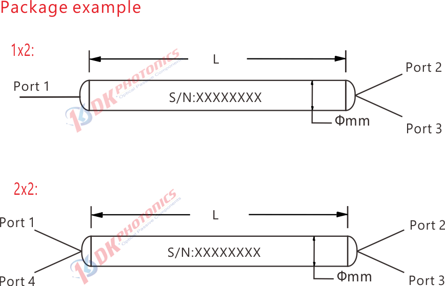
Description: 980/1030nm 1x2 Polarization Maintaining Fused WDM -2W, 1.0m PM980 Panda Fiber with 0.9mm OD loose tube, and FC/APC connectors at all ports.
If you need to customize other specifications, please provide detailed description for your requirement.
1. Function
WDM(Wavelength Division Multiplexin ) is the optical passive device, it can coupling two or more different wavelengths of light into the same optical fiber transmission. It can also be a plurality of different wavelengths of light in the same optical fiber were separated into different optical fiber transmission.
2. Characteristic
1). To combine or separate two (usually two) or more beams of light of different wavelengths.
2.) Wide operating bandwidth, low insertion loss, high channel isolation, high stability and reliability.
3). Manufactured with fused tapered technology, multiple wavelength combinations are available in the wavelength range of 450 nm-2050 nm.
3. Description
1). Fused taper structure WDM
Let’s take the FBT Coupler case, we default that there is only one energy transfer from one core to another. In fact, in the coupling region (also known as the interaction length), energy is transmitted back and forth between two fibers many times. This transmission rate is a function of wavelength, so if the wavelength used is different from the design wavelength, the energy transfer ratio (or coupling ratio) will be different.
For example, let's assume that two different wavelengths of light (red and blue) input from port 2 and port 3:
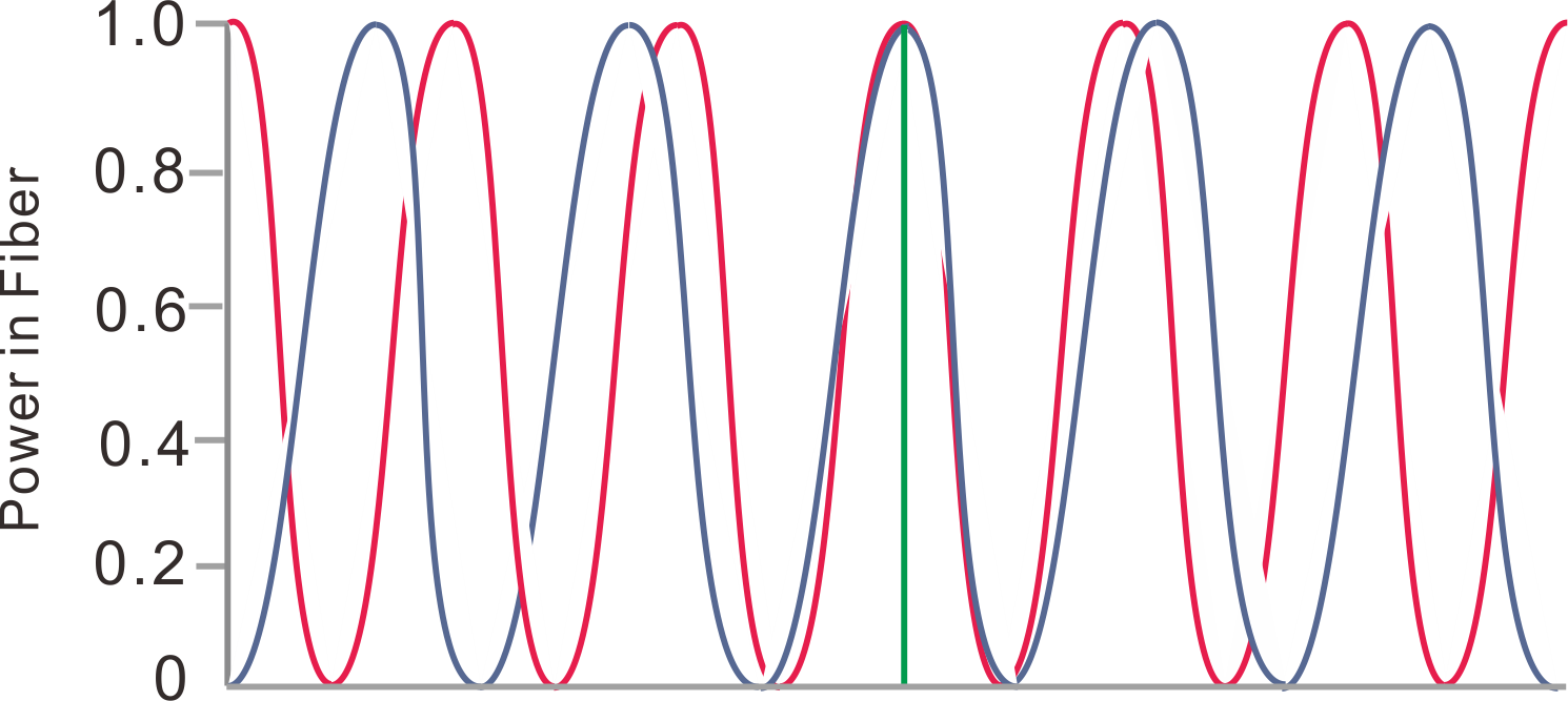
Figure 1. Curve of red and blue light energy output from port 1 with coupling length.
The energy transfer of the two wavelengths is shown in Figure 1. The horizontal axis is the length of the coupling region and the vertical axis is the output light energy of port 1. As shown in the figure, when we control the length of the coupling region to L, red light and blue light are input at the two input terminals respectively, and the output energy of the two lights at port 1 is 100%, that is to say, the light of different wavelengths input from ports 2 and 3 converge at the output of port 1.
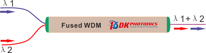
Figure 2. Schematic diagram of WDM MUX wavelengths.
Similarly, according to the principle of reciprocity of tapered devices and in combination with figure 2, when we input red light and blue light reversely from port 1, the red light and blue light will be output from two "input" terminals 2 and 3 respectively. Wavelength division multiplexing optical transmission principle of fused biconical devices: combination and separation of light with different wavelengths.
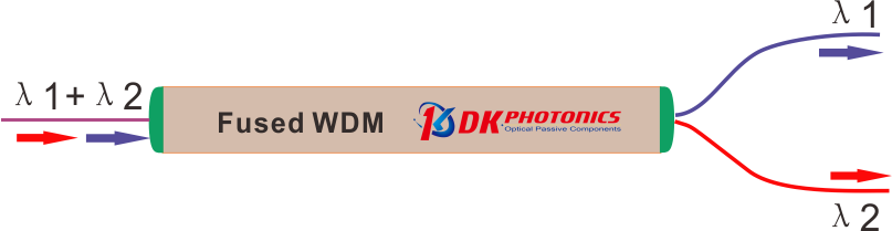
Figure 3. Schematic diagram of WDM DEMUX wavelengths.
Therefore, as long as we control the coupling length L and the spacing d between the two cores in the manufacturing process, the wavelength division multiplexing device we want can be prepared by melting taper technology.
4). The main parameters
a. IL (Insertion Loss)
The ratio of the input loss to the output loss of the passive device is defined as the additional power generated by the insertion port of the passive device:
![]()
As shown in the formula above, Pin is the power of the inverted input, Pout is the power of the inverted output. The performance of the device requires the insertion loss of forward incident light to be as small as possible (Note: Generally, the calculation result is negative, but the negative sign is often omitted in actual filling or use, the same as below.).

Figure 4.WDM schematic diagram of insertion loss test of output port 1.
As show in the Figure 4,we can see that the input port input red light power Pin =100 mW, input blue light power of Output 1 port Pout=93 mW, so the insertion loss of Output 1 is:
IL= 10 × log (100/93)
= 10 × 0.032
= -0.32 dB

Figure 5. WDM schematic diagram of insertion loss test of output port 2.
As show in the Figure 5,we can see that the input port input red light power Pin =100 mW, input red light power of Output 2 port Pout=92 mW, so the insertion loss of Output 1 is:
IL= 10 × log (100/93)
= 10 × 0.036
= -0.36 dB
b. Channel ISO (Isolation)
Isolation refers to the ability of one optical path of WDM to isolate the light in other optical paths. Each port of the coupler is designed to have low insertion loss (i.e., high transmission) at the desired wavelength while suppressing the signal at the specified wavelength of the other port, which minimizes cross talk between the ports. Therefore, isolation is specified as the insertion loss of these undesired wavelengths. High dB values of isolation are ideal for signal separation applications using a WDM.
![]()
Pin is the optical power of optical input, Pout is the optical power of not expected channel optical output.
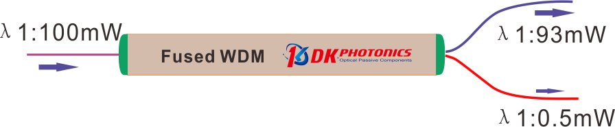
Figure 6.WDM schematic diagram of isolation loss test of output port 1.
As show in the Figure 6, Output 1 is blue light transmission channel, Output 2 red light transmission channel. Theoretically, all the blue light input from the input port should output from Output 1, but the WDM cannot completely isolate the blue light output to Output 2. Therefore, in order to show the isolation ability of WDM devices to not expected channel light, the concept of channel isolation is introduced.
As show in the Figure 6, light Input optical power of blue light Pin =100 mW, and the output power of Output 2 Pout=0.5 mW, so the ISO of Output 2 is:
ISO= 10 × log (100/0.5)
= 10 × 2.30
= 23.0dB
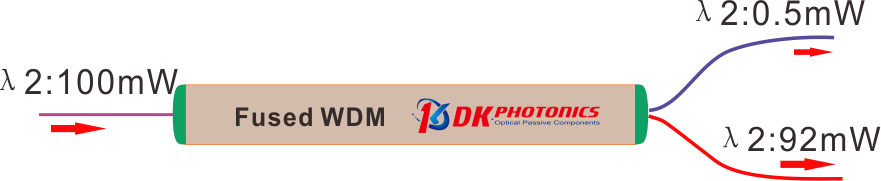
Figure 7. WDM schematic diagram of isolation loss test of output port 2.
As show in the Figure 7, Input optical power of red light Pin =100 mW, and the power of the Output 1 Pout=0.5 mW, so ISO of Output 1:
ISO= 10 × log (100/0.5)
= 10 × 2.30
= 23.0dB
c. Polarization Extinction Ratio (PER)
The polarization extinction ratio (PER) is a measure of how well a polarization-maintaining (PM) fiber or device can prevent cross coupling between the different polarization axes of the fiber. External stress on a fiber from sources such as heating, bending, or pulling can cause the PER to change.
Rotating Polarizer Method:
Rotating Polarizer Method is the most common method for measuring PER uses a low-coherence (unpolarized or circularly polarized) broadband light source and measures the extinction ratio with a linear polarizer and power meter.
The PER is measured using the following test measurement setup:
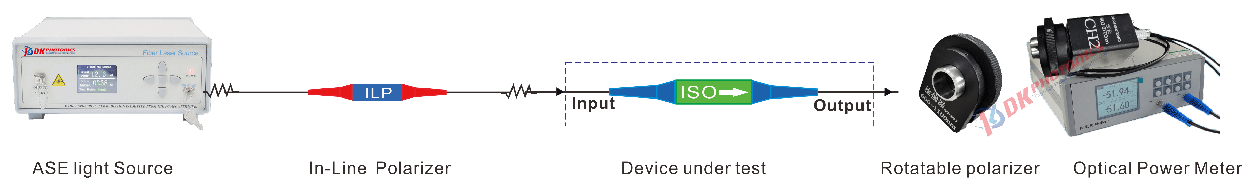
Figure 8. schematic diagram of measurement of polarization extinction ratio setup
Connect the components as shown above. Note that it is necessary to ensure that the panda eye of the PM fiber is perfectly aligned.
Adjust the rotatable polarizers sequentially until a minimum power value is measured by the power meter. Record the measured value as Pmin(dB).
Rotate the rotatable polarizers mount by 90°. Then record the measured value as Pmax(dB).
After Pmin and Pmax are measured, the extinction ratio can be calculated: PER(dB)= Pmax(dB) - Pmin(dB)
DK Photonics can provide a complete set of equipment/devices for the above measurement of extinction ratio setup, if you need it, please contact our sales: sales@dkphotonics.com.
 DownloadDatasheet in PDF