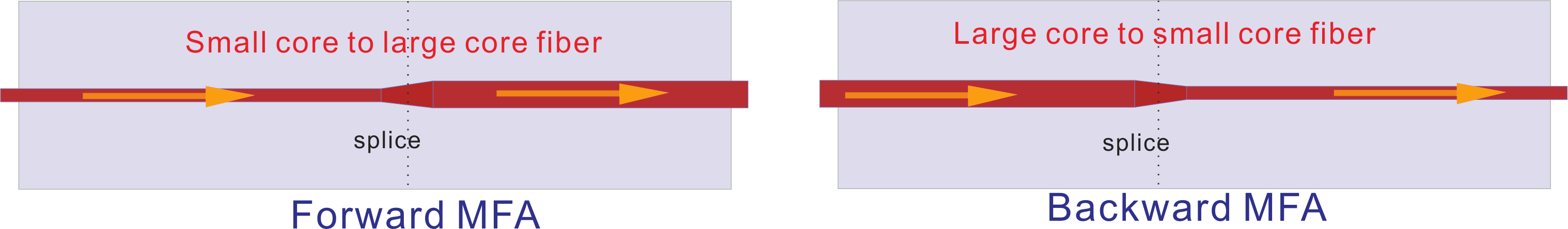
Mode field is different in fibers with different core diameter and NA. Splicing loss is large between two fibers with different mode field. In order to reduce splicing loss, mode field must be similar. MFA can optimize splice loss significantly, usually <0.5dB, even <0.3dB between different fibers.
|
Working Wavelength(nm) |
Signal Input Fiber |
Signal Output Fiber |
Signal Insertion Loss (dB) |
Max. Power Handling |
|
1950~2050 |
10/130µm, NA0.15/0.46 |
SM1950 |
≤0.5 |
20W |
|
1950~2050 |
25/250µm, NA0.09/0.46 |
10/130µm, NA0.15/0.46 |
≤0.7 |
50W |
|
1950~2050 |
PM10/130µm, NA0.15/0.46 |
PM1950 |
≤0.5 |
20W |
|
1950~2050 |
PM25/250µm, NA0.09/0.46 |
PM10/130µm, NA0.15/0.46 |
≤0.7 |
50W |
Remark:
|
Package Type
|
P1
|
P2
|
P3
|
|
Dimensions (mm)
|
Ф4.0x60
|
65x12x7
|
80x12x8
|
|
A
|
B
|
C
|
D
|
E
|
F
|
|
Working Wavelength
|
Direction
|
Power Handling
|
Input Fiber Type
|
Output Fiber Type
|
Fiber length
|
|
2000:2000nm
|
F: Forward
B: Backward
|
05:5W
25:25W
50:50W
XX:Other
|
XXX (fiber code)
|
XXX (fiber code)
|
08:0.8m(default)
10:1.0m
20:2.0m
|
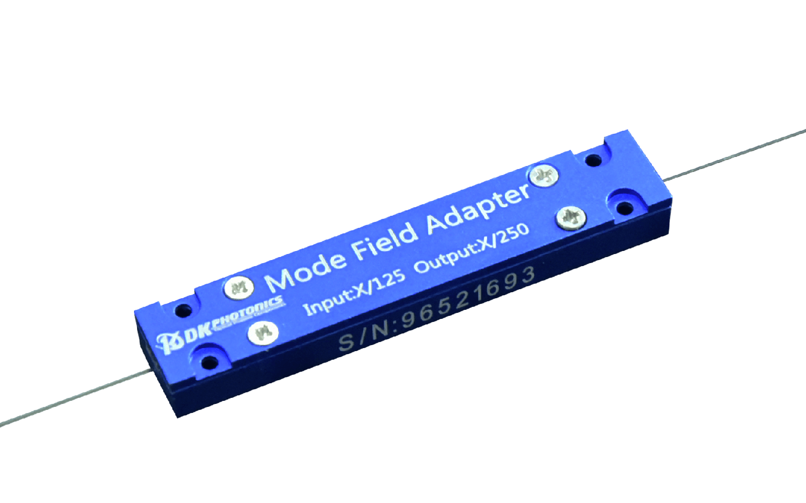
Description: 2000nm PM Mode Field Adaptor, Backward, Max. 10W power handling, PM 10/130µm, 0.15/046NA input signal fiber, PM1950 output fiber, 0.8m fiber length.
If you need to customize other specifications, please provide detailed description for your requirement.
DK
 DownloadDatasheet in PDF