Order information
P/N: PIOC-①-②-③-④-⑤-⑥-⑦
When you inquire, please provide the correct P/N number according to our ordering information and attach the appropriate description would be better. If need any connector, we do not recommend choosing a 250μm bare fiber pigtail. For high power applications, we recommend direct splicing without connectors.
|
①
|
②
|
③
|
④
|
⑤
|
⑥
|
⑦
|
|
Port
|
Operating Wavelength
|
Power Handling
|
Fiber Type
|
Fiber Diameter
|
Fiber Length
|
Connector
|
|
3:3-port
|
53:1053nm
XX: other
|
L:<0.5W
1:1W
3:3W
5:5W
10:10W
|
XX/XX/XX/XX(core/clad/core NA/clad NA)
|
25:250μm bare fiber
09:900μm Loose Fiber
XX: Others
|
05:0.5m
10:1.0m
15:1.5m
XX:Others
|
00: None
FP: FC/PC
FA: FC/APC
XX: Others
|
Part Number Example: PIOC-3-53-2-06X-25-10-00
Description: 1053nm 3-port TGG Based Polarization Insensitive Optical Circulator, 2W power handling, 1060-XP fiber, with bare fiber, 1.0m length fiber pigtails, without connectors.
Ordering Information for Custom Parts:
If you need to customize other specifications, please provide detailed description for your requirement.
Fiber Optical Circulator
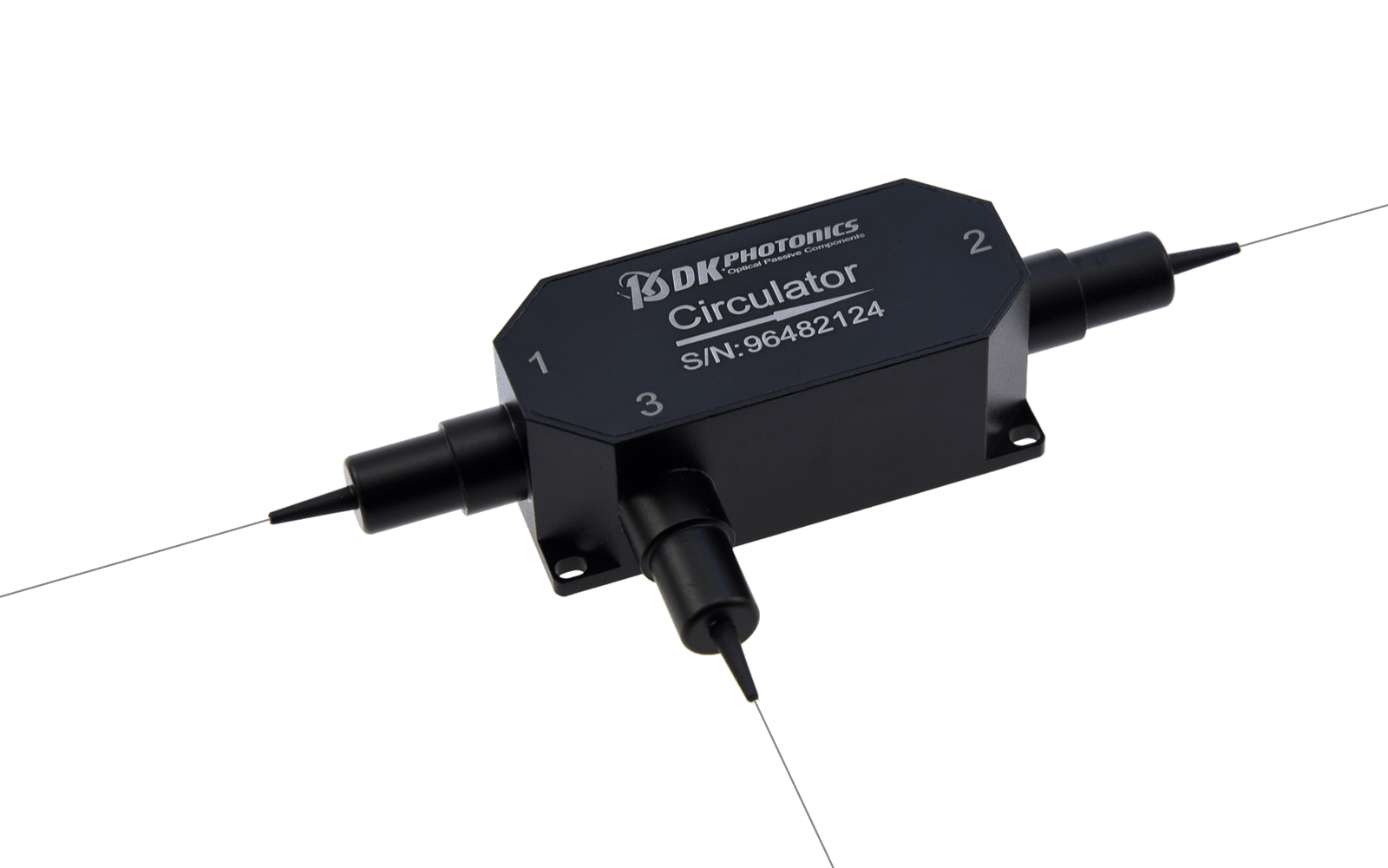
1. Definition
Optical circulator is a multiport optical device which has nonreciprocal properties. When the optical signal is input from any port, it would output from the next port in digital order with small loss: if a signal is input from port 1, the signal can only be output from port 2. Similarly, the signal input from port 2 can only be output from port 3. That's why it's called a circulator.
2. Characteristic
1). Unidirectional transmission, non-Reciprocating
2). High isolation, low insertion loss
3). High stability and reliability.
3. Description
1). Principle introduction
Optical circulator is a multiport optical device which has nonreciprocal properties, The typical structure has N ports(N≥3). As shown in Figure 1, when the light is input from port 1, it would output from port 2 with almost no loss, and other ports have almost no light output; When the light is input from port 2, it would output from port 3 with almost no loss, and other ports have almost no light output. And so on. these three ports form a continuous channel. Strictly speaking, if the light input from port 3 can be output from port 1, it is called a circulator. If the light input from port 3 cannot be output from port 1, it is called a quasi circulator;Usually we do not make a strict distinction in the name, so it is generally called circulator.
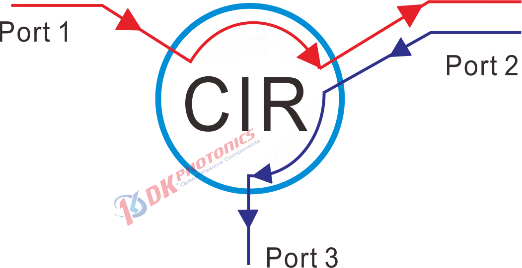
Figure 1 Basic function of a three-port optical circulator
Figure 2 illustrates the configuration of a polarization-independent optical circulator. Similar to a polarization-independent optical isolator, an optical circulator also uses YVO4 birefringence material as beam displacers and Bi-YIG for Faraday rotators. However, configuration of an optical circulator is obviously much more complex than an isolator because the backward-propagated light must be collected at port 3.
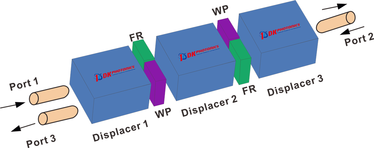
Figure 2. Configuration of a polarization-insensitive optical circulator.
2). Applications
- Add-Drop Multiplexing
- Fiber Sensors
- Bidirectional Pumping
- Bidirectional Signal Transmission Systems
- Coupling In-Line Chromatic Dispersion Compensation Devices
Because of its high isolation and low insertion loss, optical circulators are widely used in advanced communication systems as add-drop multiplexers, bi-directional pumps, and chromatic dispersion compensation devices.
Circulators can also be used to send optical signal in two directions down a single fiber. A circulator is located at both ends of the fiber. Each circulator functions to add a signal in one direction while removing the signal in the other. See the Figure 3.
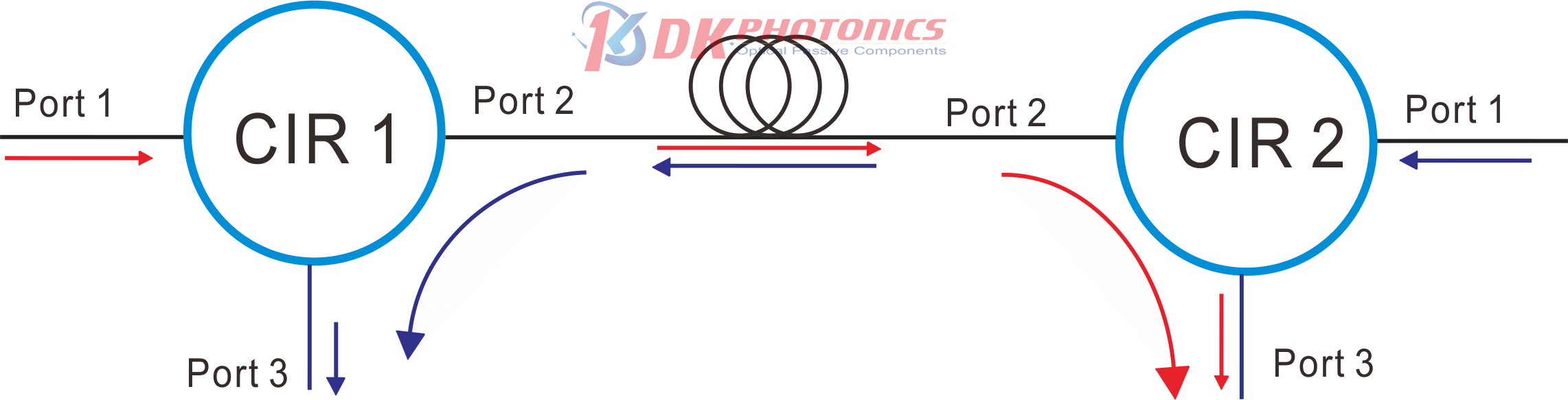
Figure 3. Optical circulator applications for Bidirectional Signal Transmission Systems
3). Key parameters
The technical parameters of optical circulator include insertion loss, isolation, crosstalk, polarization dependent loss, polarization mode dispersion and return loss. The definitions of insertion loss, isolation, polarization dependent loss and polarization mode dispersion of optical circulator are basically the same as those of optical isolator, but for circulator, they all refer to specific indicators between two adjacent ports, such as insertion loss between Ports 1 and 2 or between ports 2 and 3.
Insertion Loss(IL)
The insertion loss is defined as the ratio of the input power to the output power at one of the output legs of the coupler (signal or tap). Insertion loss is always specified in decibels (dB). It is generally defined using the equation below:
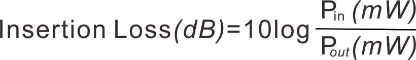
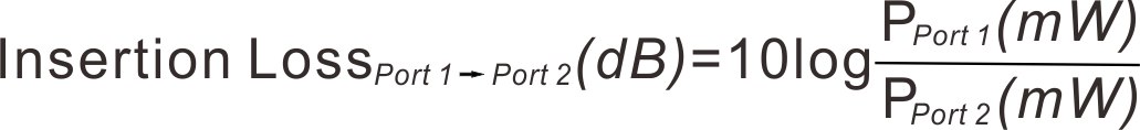
where Pin and Pout are the input and output powers (in mW). For our 3 port fiber optical circulator, the insertion loss specification is provided for both port 2 and port 3 outputs; our specifications always list insertion loss for the signal output first. To define the insertion loss for a specific output (port 2 or port 3), the equation is rewritten as:

Isolation(ISO)
Isolation refers to the isolation ability of the optical circulator to reverse reflected light. It is defined as the decibel ratio of the power value of the reverse incident optical signal to the power value of the reverse output optical signal:
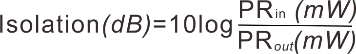
As shown in the formula above, PRin is the power of the inverted input, PRout is the power of the inverted output. The performance of the device requires the higher isolation, the greater the isolation value of reflected light, the better.
Polarization Dependent Loss (PDL)
The polarization dependent loss is defined as the ratio of the maximum and minimum transmissions due to polarization states in fiber optical circulator. This specification pertains only to fiber optical circulator not designed for maintaining polarization. PDL is always specified in decibels (dB), and can be calculated with the following equation:
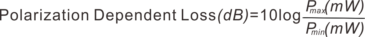
where Pmax is the maximum power able to be transmitted through the coupler when scanning across all possible polarization states. Pmin is the minimum transmission across those same states.
Return Loss (RL)
The return loss refers to the fraction of input light that is lost in the internally terminated fiber end within the coupler housing when any port is used as the input. It can be calculated in units of dB using the following equation:
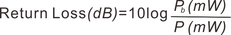
where P and Pb are the optical powers (in mW) in any port and the internally terminated fiber, respectively. This output is the result of back reflection at the junction of the legs of the coupler.
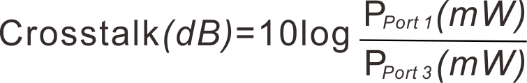
Crosstalk
Crosstalk of optical circulator refers to the relative value in dB of the power received between two non-adjacent ports that cannot receive optical signals in theory. Due to various reasons in practice, the dB value of the power received at port 3 relative to the input power when the input signal of port 1 is used.Crosstalk between two port (port 1 and port 3) is referred to as directivity:
The light reflected from the fiber optical circulator must be minimal so as not to interfere with the measurement signal. The sources of interference are kept as small as possible. This includes assembly and packaging of the connectors.
When testing crosstalk, make sure that Port 2 does not have any light input, including natural light such as electric lights and sunlight. If the port has a connector, you need to remove the dust cap, because some dust caps will reflect light. Then wrap the Port 2 fiber with a diameter of less than 10mm(only for125um cladding fiber) for more than 3 turns, as shown in the figure 4 below:
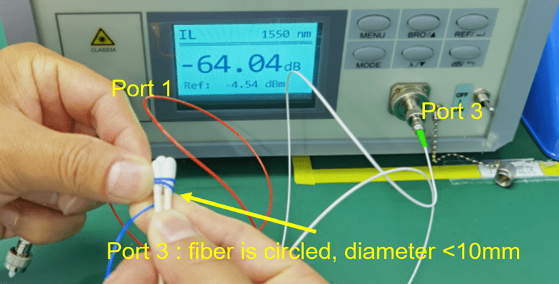
Figure 4. How to test crosstalk of optical circulator
 DownloadDatasheet in PDF