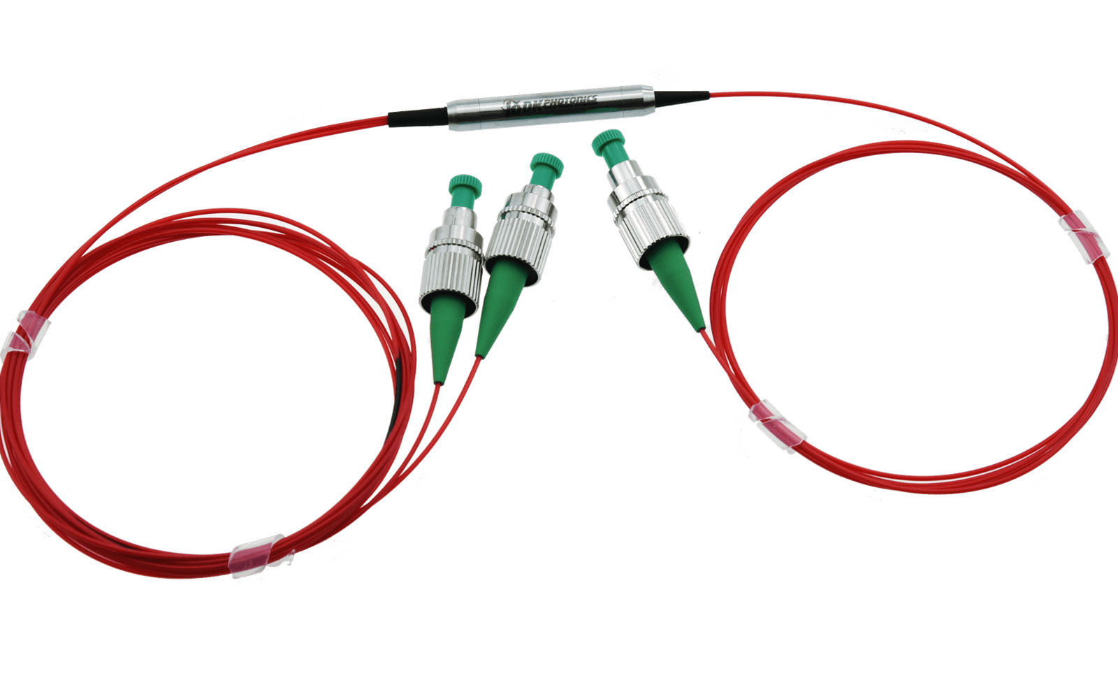
The 1030nm polarization maintaining optical circulator is a compact, high performance light wave component that routes incoming signals from Port 1 to Port 2, and incoming Port 2 signals to Port 3. So fiber optic circulators act as signal routers, transmitting light from an input fiber to an output fiber, but directing light that returns along that output fiber to a third port.
The 1030nm polarization maintaining optical circulator is a compact, high performance light wave component that routes incoming signals from Port 1 to Port 2, and incoming Port 2 signals to Port 3. So fiber optic circulators act as signal routers, transmitting light from an input fiber to an output fiber, but directing light that returns along that output fiber to a third port. They perform a similar function as an isolator, protecting the input fiber from return power, but also allowing the rejected light to be employed.
If you do not see a standard Optical Circulator that meets your needs, we welcome the opportunity to review your desired specification and quote a custom circulator. Requests for custom fiber pigtails, different wavelengths and handling power of operation or other specific needs will be readily addressed.
|
Parameter |
Unit |
Values |
|
Axis |
- |
Fast axis blocked |
|
Center Wavelength |
nm |
1030 |
|
Port |
- |
3 |
|
Isolation level |
- |
Type B |
|
Operating Wavelength Range |
nm |
± 5 |
|
Min. Isolation at 23℃ |
dB |
20 |
|
Typ. Isolation at 23℃ |
dB |
25 |
|
Peak Isolation at 23℃ |
dB |
/ |
|
Typ. Insertion Loss at 23℃ |
dB |
3.5 |
|
Max. Insertion Loss at 23℃ |
dB |
3.8 |
|
Min. Extinction Ratio at 23℃ |
dB |
20 |
|
Min. Return Loss |
dB |
50 |
|
Min. Cross Talk |
dB |
50 |
|
Max. Power Handling (total input, continuous wave) |
W |
0.05 |
|
Max. Tensile Load |
N |
5 |
|
Fiber Type |
- |
PM980-XP Panda Fiber |
|
Operating Temperature |
℃ |
-5 to +70 |
|
Storage Temperature |
℃ |
-40 to +85 |
|
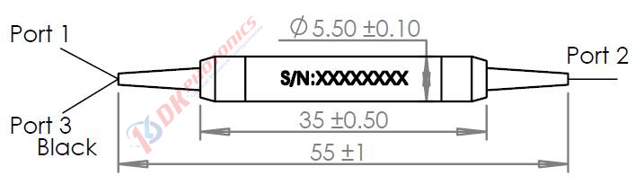
Package Dimensions |
mm |
Ø5.5 x L35 |
|
①
|
②
|
③
|
④
|
⑤
|
⑥
|
⑦
|
⑧
|
⑨
|
|
Port
|
Operating Wavelength
|
Axis
|
Isolation level
|
Power Handling
|
Fiber type
|
Pigtails Diameter
|
Fiber Length
|
Connector
|
|
3:3-port
|
30:1030nm
XX: Others
|
F: Fast axis blocked
|
B: Type B
|
L:<0.05W
|
P98X:PM980-XP
XX: Others
|
25:250μm bare fiber
90:900μm Loose tube
XX: Others
|
05:0.5m
10:1.0m
15:1.5m
XX: Others
|
00: None
FP: FC/PC
FA: FC/APC
XX: Others
|
Ordering Information for Custom Parts
If you need to customize other specifications, please provide detailed description for your requirement.
1. Definition
Optical circulator is a multiport optical device which has nonreciprocal properties. When the optical signal is input from any port, it would output from the next port in digital order with small loss: if a signal is input from port 1, the signal can only be output from port 2. Similarly, the signal input from port 2 can only be output from port 3. That's why it's called a circulator.
2. Characteristic
1). Unidirectional transmission, non-Reciprocating
2). High isolation, low insertion loss
3). High stability and reliability.
3. Description
1). Principle introduction
Optical circulator is a multiport optical device which has nonreciprocal properties, The typical structure has N ports(N≥3). As shown in Figure 1, when the light is input from port 1, it would output from port 2 with almost no loss, and other ports have almost no light output; When the light is input from port 2, it would output from port 3 with almost no loss, and other ports have almost no light output. And so on. these three ports form a continuous channel. Strictly speaking, if the light input from port 3 can be output from port 1, it is called a circulator. If the light input from port 3 cannot be output from port 1, it is called a quasi circulator;Usually we do not make a strict distinction in the name, so it is generally called circulator.
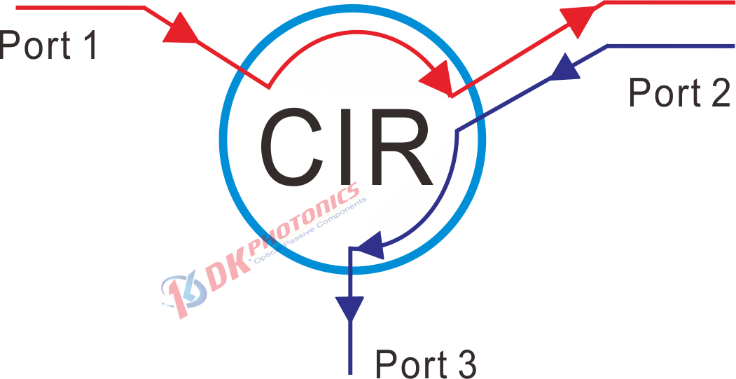
Figure 1 Basic function of a three-port optical circulator
Figure 2 illustrates the configuration of a polarization-independent optical circulator. Similar to a polarization-independent optical isolator, an optical circulator also uses YVO4 birefringence material as beam displacers and Bi-YIG for Faraday rotators. However, configuration of an optical circulator is obviously much more complex than an isolator because the backward-propagated light must be collected at port 3.
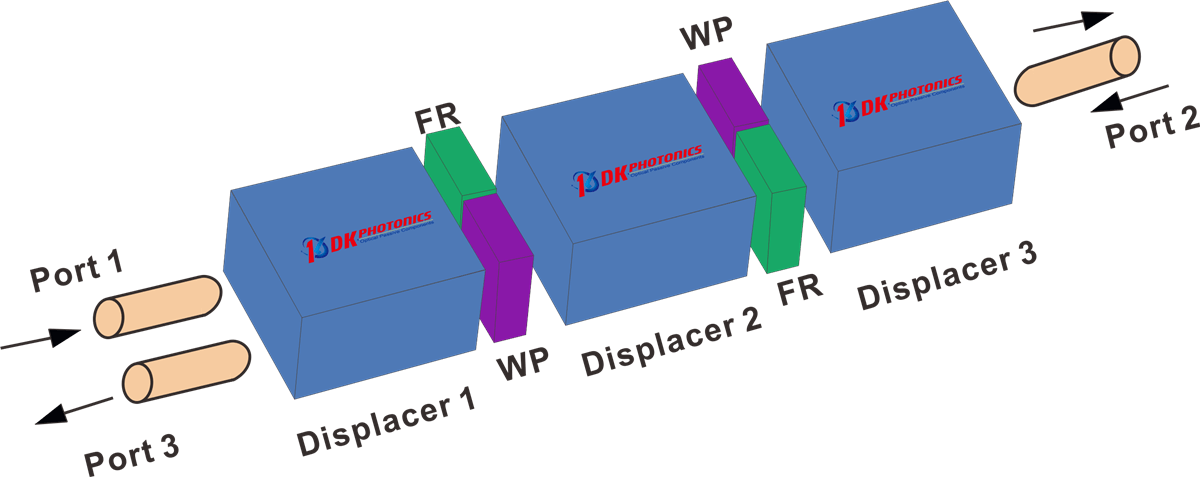
Figure 2. Configuration of a polarization-insensitive optical circulator.
2). Applications
Because of its high isolation and low insertion loss, optical circulators are widely used in advanced communication systems as add-drop multiplexers, bi-directional pumps, and chromatic dispersion compensation devices.
Circulators can also be used to send optical signal in two directions down a single fiber. A circulator is located at both ends of the fiber. Each circulator functions to add a signal in one direction while removing the signal in the other. See the Figure 3.
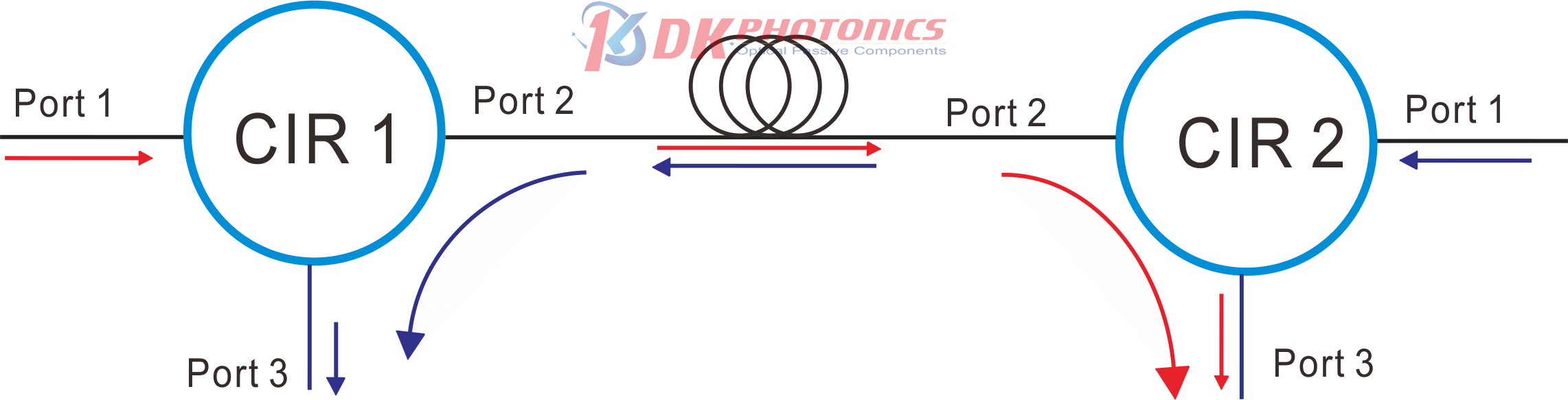
Figure 3. Optical circulator applications for Bidirectional Signal Transmission Systems
3). Key parameters
The technical parameters of optical circulator include insertion loss, isolation, crosstalk, polarization dependent loss, polarization mode dispersion and return loss. The definitions of insertion loss, isolation, polarization dependent loss and polarization mode dispersion of optical circulator are basically the same as those of optical isolator, but for circulator, they all refer to specific indicators between two adjacent ports, such as insertion loss between Ports 1 and 2 or between ports 2 and 3.
Insertion Loss(IL)
The insertion loss is defined as the ratio of the input power to the output power at one of the output legs of the coupler (signal or tap). Insertion loss is always specified in decibels (dB). It is generally defined using the equation below:
![]()
where Pin and Pout are the input and output powers (in mW). For our 3 port fiber optical circulator, the insertion loss specification is provided for both port 2 and port 3 outputs; our specifications always list insertion loss for the signal output first. To define the insertion loss for a specific output (port 2 or port 3), the equation is rewritten as:
![]()
![]()
Isolation(ISO)
Isolation refers to the isolation ability of the optical circulator to reverse reflected light. It is defined as the decibel ratio of the power value of the reverse incident optical signal to the power value of the reverse output optical signal:
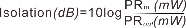
As shown in the formula above, PRin is the power of the inverted input, PRout is the power of the inverted output. The performance of the device requires the higher isolation, the greater the isolation value of reflected light, the better.
Polarization Extinction Ratio (PER)
The polarization extinction ratio (PER) is a measure of how well a polarization-maintaining (PM) fiber or device can prevent cross coupling between the different polarization axes of the fiber. External stress on a fiber from sources such as heating, bending, or pulling can cause the PER to change.
![]()
Rotating Polarizer Method:
Rotating Polarizer Method is the most common method for measuring PER uses a low-coherence (unpolarized or circularly polarized) broadband light source and measures the extinction ratio with a linear polarizer and power meter.
The PER is measured using the following test measurement setup:
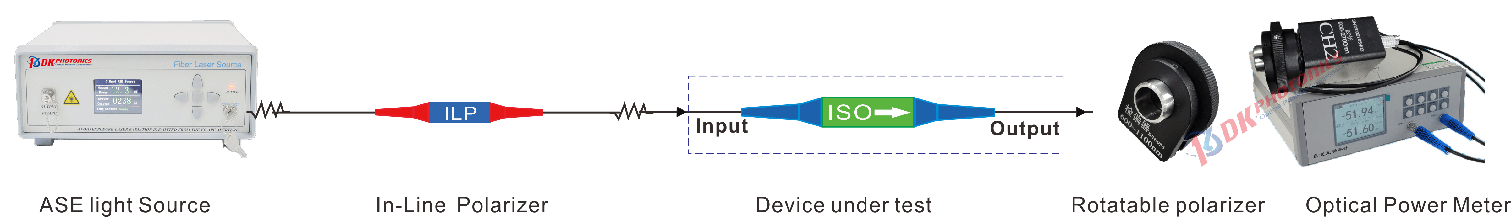
Figure 4. schematic diagram of measurement of polarization extinction ratio setup
Connect the components as shown above. Note that it is necessary to ensure that the panda eye of the PM fiber is perfectly aligned.
Adjust the rotatable polarizers sequentially until a minimum power value is measured by the power meter. Record the measured value as Pmin(dB).
Rotate the rotatable polarizers mount by 90°. Then record the measured value as Pmax(dB).
After Pmin and Pmax are measured, the extinction ratio can be calculated: PER(dB)= Pmax(dB) - Pmin(dB)
DK Photonics can provide a complete set of equipment/devices for the above measurement of extinction ratio setup, if you need it, please contact our sales: sales@dkphotonics.com.
Return Loss (RL)
The return loss refers to the fraction of input light that is lost in the internally terminated fiber end within the coupler housing when any port is used as the input. It can be calculated in units of dB using the following equation:
![]()
where P and Pb are the optical powers (in mW) in any port and the internally terminated fiber, respectively. This output is the result of back reflection at the junction of the legs of the coupler.
Crosstalk
Crosstalk of optical circulator refers to the relative value in dB of the power received between two non-adjacent ports that cannot receive optical signals in theory. Due to various reasons in practice, the dB value of the power received at port 3 relative to the input power when the input signal of port 1 is used.Crosstalk between two port (port 1 and port 3) is referred to as directivity:
![]()
The light reflected from the fiber optical circulator must be minimal so as not to interfere with the measurement signal. The sources of interference are kept as small as possible. This includes assembly and packaging of the connectors.
When testing crosstalk, make sure that Port 2 does not have any light input, including natural light such as electric lights and sunlight. If the port has a connector, you need to remove the dust cap, because some dust caps will reflect light. Then wrap the Port 2 fiber with a diameter of less than 10mm(only for125um cladding fiber) for more than 3 turns, as shown in the figure 4 below:
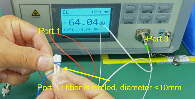
Figure 5. How to test crosstalk of optical circulator
 DownloadDatasheet in PDF