Pump and signal combiner for bi-directional pumping of all-fiber lasers and amplifiers(2)

2. Optical design and relevant ray paths of the fiber combiner

A schematic side view of the side-pump combiner consisting of a pump feeding fiber (PFF), a coreless intermediate fiber (IF) and a target fiber (TF) is shown in Fig. 1

high-power-isolator-1064nm

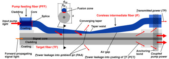
Fig. 1 Schematic side view of a side-pumped double-clad fiber including important ray paths.

. The diameter of the PFF core and the cladding was 105 and 125 µm, respectively. The NA of the pure silica PFF core used in the simulations was 0.15, 0.22 or 0.3 and, therefore, the refractive index of the PFF cladding was depressed in comparison to the refractive index of the PFF core. The cladding of the PFF was surrounded by a polymer coating only for mechanical protection of the fiber. Therefore, the PFF preserved the same waveguide properties after removal of the polymer coating. In the case of side-pumping without an IF, the higher refractive index of the core of the PFF would suppress the pump power transfer into the TF as long as the PFF is untapered. An increase of the NA of the pump light due to tapering of the PFF would result in an increase of the pump power transfer, though only for rays that exceed the NA of the PFF core. Thus, it is especially difficult to couple pump light rays with a low NA into the TF. Unfortunately, this type of PFF is typically used as high power delivery fiber of pump diodes. To overcome this problem, without removing the glass cladding of the PFF, a coreless IF was inserted in the fiber combiner setup. At first the ~30 cm long IF with a cladding diameter of 125 µm was fusion spliced to the PFF. The IF had a NA of 0.46 due to the refractive index difference (Δn) between fused coupler silica and the outermost polymer coating. After removing the polymer coating (e.g. with acetone) along a certain section of the IF (~15 mm), the IF was individually tapered, and afterwards the converging taper portion was laterally fused with the TF. The fusion level (FL) is defined as FL=(2z)/(dIF+dTF), where dIF and dTF are the cladding diameters of the IF and the TF at a certain taper position, respectively, and z represents the distance of the fused IF and TF, as depicted in Fig. 1. The FL was experimentally determined by measuring dIF, dTF and z at different positions along the converging taper portion with an optical microscope. With this measurement an averaged very low FL of 1.99 was determined, which was also used for the simulations. The overlap area between the TF and the IF is defined as the fusion zone. In contrast to the converging taper portion, the diverging taper portion of the IF was not fused to the TF, but placed under a small angle to the fiber axis of the TF, resulting in a small air gap between the IF and the TF. The employed TF was a DC fiber with a core diameter of 25 µm (NA 0.06) and a cladding diameter of 250 µm (NA 0.46). The cladding of the TF was also surrounded by a polymer coating, except along the coupling region of the combiner. The low index coating had to match the mechanical and additionally the optical properties of the DC fiber. An anchoring bond was used to fix the fiber bundle on each side on a copper substrate. Figure 1 shows the anchoring bond only on the right-hand side without the copper substrate. Additionally, the anchoring bond served as a pump light stripper for rays which do not satisfy the NA criterion of the TF.

Before proceeding with a more detailed investigation with the aid of simulations in the next section, we will qualitatively discuss some important ray paths of the fiber combiner. Pump light rays guided into the PFF and entering the tapered portion of the IF increase in NA as long as the rays propagate along the converging taper. As a rule of thumb, the pump light input NA increases by a factor of the taper ratio (TR), which is defined as the ratio of the original fiber diameter to the diameter of the taper waist. Pump light coupling into the TF occurs as soon the rays enter the fusion zone. The converging taper portion increases the probability for pump light transfer into the TF, since the number of ray-bounces along the lateral surface of the IF increases. Particularly, pump light rays with a low input NA couple more efficiently due to the converging taper.

Pump light rays remaining in the IF, and consequently not coupling into the TF, can occur as transmitted power (TP: transmittedpower, Fig. 1) or power leakage into the ambient air (PAA: power leakage into the ambient air, Fig. 1). As long as the condition for internal total reflection is satisfied, the pump light rays are detected as TP, otherwise the rays escape into the ambient air as PAA. The angle of total internal reflection for the uncoated IF is 43.6°, since Δn between fused silica and air is 0.45 at a wavelength of 976nm pump laser protector, which means the IF can guide light up to a theoretical NA of 1.05. Of course, the NA cannot exceed 1.0. Therefore, pump light rays with a theoretical NA in the range of more than 1.0 up to 1.05 would experience total reflection in the case of an existing fiber endface. Pump light rays which exceed the theoretical NA of 1.05 occur as PAA.

For almost loss-free pump light coupling into the TF it is necessary that the rays enter the TF before they exceed the cladding NA of the TF of 0.46. This desired coupling behavior can usually be achieved by adapting the taper parameters. However, pump light coupling for rays with an NA far above 0.46 cannot be completely suppressed. Unfortunately, this pump power leakage couple into the coating of the TF (PCT: power leakage into the coating of the target fiber) and can damage it.

In summary, the input pump combiner will be divided into the coupled pump power and the losses including PAA, PCT and TP (Fig. 1).

Pump and signal combiner for bi-directional pumping of all-fiber lasers and amplifiers(1)

Abstract

We developed an all-fiber component with a signal feedthrough capable of combining up to 6 fiber-coupled multi-mode pump sources to a maximum pump power of 400 W at efficiencies in the range of 89 to 95%, providing the possibility of transmitting a high power signal in forward and in reverse direction. Hence, the fiber pump combiner can be implemented in almost any fiber laser or amplifier architecture. The complete optical design of the combiner was developed based on ray tracing simulations and confirmed by experimental results.

(N+1)X1 Pump and Signal Combiner

1. Introduction

For the realization of compact, reliable, rugged and efficient monolithic high power fiber laser systems, the efforts of integrating all-fiber components have been increased in recent years [1,2]. A key component of a highly integrated fiber laser or amplifier system is a high power all-fiber signal and pump combiner.

The most common type of fiber combiner, a fused tapered fiber bundle (TFB) [3,4], is based on the fiber end face pumping technique and is probably the most sophisticated pump combiner capable of handling several hundred watts of pump power [5]. A TFB with signal feedthrough consists of a central input signal fiber, guiding the signal light, surrounded by several multi-mode fibers, guiding the pump light, and an output pigtail double-clad (DC) fiber which combines the signal and pump light in a single pigtail fiber. In order to match the diameter of the fiber bundle to the diameter of the output pigtail fiber, the bundle is slowly melted and tapered. After the tapering process the fiber bundle is cleaved around the taper waist and fusion spliced to the output pigtail DC fiber. However, tapering of the fiber bundle inherently involves increasing the numerical aperture (NA) of the pump light and a change of the mode field diameter (MFD) of the signal light. Hence, the necessary optical matching and mechanical alignment requirements between the tapered fiber bundle and the output pigtail DC fiber can lead to several drawbacks of the TFB structure: (1) less flexibility in the choice of input fibers that match the output pigtail DC fiber after the tapering process, (2) a slight mismatch or misalignment between the signal mode field diameters (MFD) of the tapered input signal fiber and the output pigtail DC fiber leads to a degradation of the beam quality, primarily in conjunction with signal insertion loss, and (3) in the case of a backward propagating signal, e.g. for a counter-propagation pumped fiber amplifier, the signal insertion loss (up to 10%) can cause damage to the pump diodes due to their insufficient isolation against amplified signal light.

A more promising approach to overcome these problems is side-pumping technology, which involves coupling the pump light via the outermost cladding surface into the fiber. The key advantage of this technology is the uninterrupted signal core, eliminating the need for an additional fusion splice in conjunction with signal mode matching. In recent years several proposals for side-pumping of DC fibers have been reported, such as V-groove side pumping [6], a mirror embedded in the inner cladding of a DC fiber [7] or side-coupling by an angle polished pump fiber [8]. However, for most of these side-pumping configurations it is difficult to reach the mechanical accuracy required for a stable and efficient pump light coupling.

A more rugged approach is a monolithic all-fiber combiner like the GT-Wave coupler [9], the employment of a tapered capillary around a multi-clad fiber [1011] or direct fusion of one or more tapered multi-mode fibers to the outermost cladding of multi-clad fibers [1214]. In Ref [11] seven pump delivery fibers with a core diameter of 110 µm (NA 0.22) were combined and laterally coupled via a tapered capillary into a DC fiber with a core diameter of 400 µm (NA 0.46), which led to a combined pump power of 86 W with a coupling efficiency of ~80%. In Ref [13], direct lateral fusion of one tapered pump delivery fiber with a core diameter of 200 µm (NA 0.46) to a DC fiber of 250 µm (NA 0.46) led to a coupling efficiency of 90% at a pump input power of 120 W, furthermore, a pump delivery fiber with a diameter of 400 µm (NA 0.46) was used to couple a pump power of 300 W with an efficiency of 85% into a DC fiber with a diameter of 400 µm (NA 0.46). These impressive coupling efficiencies for one pump port were achieved by use of a straight and a tapered fiber section, allowing for highly efficient coupling of pump light rays with a high numerical aperture. Thus, in Ref [13] the impact of the straight fiber section on the side-pump coupling process was discussed. However, a review of the literature reveals that the impact of the fiber and taper parameters on the pump coupling behavior as well as the loss mechanism have not yet been investigated in detail for side-pumped combiners based on direct fusion of one or several tapered multi-mode fibers to the outermost cladding of a DC fiber.

We report detailed simulations and experiments for a component which combines up to 6 multi-mode fibers with a core diameter of 105 µm (NA 0.15 or 0.22) into a DC fiber with a cladding diameter of 250 µm (NA 0.46) via side-coupling. Firstly, we explain the principle of the optical design of the fiber combiner. For a fiber combiner with a single pump port, the achievable pump coupling efficiency and the corresponding loss mechanisms were investigated. For multiple pump ports, the simulations and experiments showed that with each additional pump port, the taper parameters need to be adjusted in comparison to a single pump port configuration. These simulation results can also be used as an estimation for fiber combiners, which combine one or several multi-mode fibers with a core diameter of 200 µm (NA 0.22) into a DC fiber with a cladding diameter of 400 µm (NA 0.46). Therefore, this work covers two important fiber combiner types, since active fibers with cladding diameters of 250 or 400 µm are typical sizes provided by fiber manufacturers and used for continuous wave and pulsed laser systems. In addition, we also investigated the signal feedthrough of the combiner. We demonstrated a low signal insertion loss, maintenance of an excellent signal beam quality and an efficient isolation of the pump diodes against signal light in the case of a reverse propagating signal. The preservation of the signal light properties by the fiber combiner was utilized in Ref [15] for the realization of a counter-propagation pumped single-frequency fiber amplifier with an amplified signal power of 300 W.

What is Pump Laser Protector, Where is the Pump Laser Protector use?

The Pump Laser Protector (also called Pump Protection Filters) is a passive component which allows maximum transmission from a discrete fibre-coupled pump laser diode and blocks parasitic signals around the centre wavelength of the laser from being reflected back into the laser.

Pump Laser Protector
Multimode Pump Laser Protector -10~30W

Single-emitter laser diodes are highly regarded for their long term reliability. However, these devices are very sensitive to backward propagating light within the delivery fiber. Backward power imaged onto the diode material, as small as 5% of the pump diode output, can cause accelerated diode degradation and, in the majority of cases, catastrophic failure.That is why we need Pump Laser Protector.

DK Photonics offers filter technology that provides protection to pump diodes under these conditions (up to 50 dB Backward Signal Attenuation). Splicing these filters to the pump output fiber rejects unwanted light before it reaches the diode.

Multimode Pump Protection filters are available for a wide range of standard light emitting diodes. Fiber pigtails are 105/125 micron, with both 0.15 and 0.22 NA cores and 50/125 or 62.5/126 MM fiber available. Operating wavelengths cover the majority of diode laser lines (915 nm, 940 nm, 960 nm and 976) and maximum power handling is 25W without water-cooling.DK Photonics recently released a new type of Pump Laser Protector up to 200W handling power with water-cooling technology. And also have SingleMode Pump Laser Protector with Hi1060 fiber for 976nm fiber laser.

If you do not see a Pump Laser Protector from the standard configurations that meets your needs, we welcome the opportunity to review your desired specification and quote a filter best suited to your application. Different pump/rejection wavelengths or fiber pigtail can be accommodated.

DK Photonics – www.dkphotonics.com specializes in designing and manufacturing of high quality optical passive components mainly for telecommunication, fiber sensor and fiber laser applications,such asDK Photonics' promotion products including:High Power Isolator,1064nm Components,PM Components,Pump Combiner,Pump Laser Protector,which using for fiber laser applications.Also have Mini-size CWDM, Optical Circulator, PM Circulator,PM Isolator, Fused Coupler,Mini Size Fused WDM.More information,please contact us.