WDM-PON technology-DK Photonics

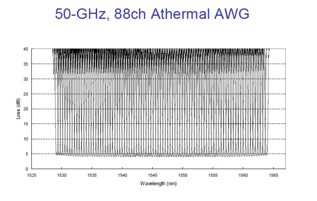
WDM-PON provides the dedicated bandwidth of a point-to-point network and the fiber sharing inherent in PONs. The architecture is somewhat similar to that of EPON and GPON; instead of the power-splitter approach used in TDM-PON architectures, WDM-PON uses an arrayed waveguide grating (AWG) filter that separates the wavelengths for individual delivery to the subscriber ONUs (see Figure 1).

A simple, plug-and-play implementation is based on wavelength-locked or tunable lasers. Self-tuning “colorless” ONUs can be used at the subscriber sites to simplify inventory and spare-part handling. Colorless optics not only simplify operations, but also reduce deployment costs, since they don’t need the expensive wavelength-stability components that traditional fixed and tunable optics require. There are multiple approaches to the colorless ONU technology.

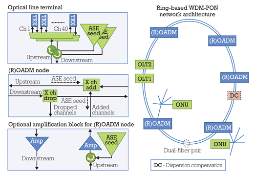
In one approach, the wavelength of the ONU transmitter is controlled by injection of a “seed” signal into the transmitter (e.g., a wavelength-locked Fabry-Perot laser or reflective semiconductor optical amplifier). The seed signal injected into the transmitter could come from broadband ASE light sliced through the filters in the system or from a DFB laser array. In a self-seeding version of this approach, the seed light is provided by feedback of broadband light from the transmitter itself. The passive filtering of the seed light in the remote node determines the wavelength of the ONU transmitter.

In a different approach, the colorless ONU contains a singlemode optic coupler wavelength-tunable laser, which is able to tune to the appropriate wavelength that matches the remote node filter port.

Below 10-Gbps channel bit rates, the injection-seeded method provides a cost-efficient approach. As an example, a wavelength-locked Fabry-Perot transmitter can be integrated into an MSA SFP pluggable form-factor module, which enables the use of third-party CPE devices. A modified EDFA gain block in a 70×90 MSA form factor could be used to generate the broadband ASE light that’s used as a seed signal in the system.

At 10-Gbps bit rates, tunable-laser technology offers an alternative to the injection-seeded approach. The tunable-laser technology developed for the metro/long-haul market has matured significantly over the past couple of years and is able to give a good cost-per-bit ratio when high capacity is needed.

If the WDM-PON system is properly designed, then it’s possible to mix different transmission technologies. By following certain design rules during the installation of the WDM-PON system, it’s possible to allow step-wise channel upgrades to higher bit rates when the demand arises. These design rules ensure that channel OSNR requirements will be met in the presence of reflections and that inter-channel crosstalk is avoided. The result is an open and flexible access network that can support many applications and services over the same infrastructure. WDM-PON thus becomes an optical option for the access network as and where it makes sense.

Given its ability to help service providers cope with current bandwidth demands as well as the next potential broadband access bottleneck, WDM-PON100GHz DWDM Module is becoming an important technology to consider in terms of its benefits and market timing. As with any emerging technology, service providers need to consider the optimal strategy for initial deployment of WDM-PON. That includes how they could use WDM-PON for additional network applications as the technology matures and its costs come down.

 WDM-PON technology

WDM-PON technology

FIGURE 2. Architectural scenario explored in the collaboration between Transmode and Deutsche Telekom Hochschule für Telekommunikation.

The latest generations of WDM-PON systems are now gaining traction with operators around the globe for field deployment, lab trials, and evaluations. It’s clearly the early stage of WDM-PON deployments, but progress has started and 2014 looks to be a pivotal year for the technology.

WDM-PON is a key component in next generation access(1)

Many industry analysts believe that the increasing requirements for bandwidth scalability, quality of service, and support of the emerging traffic patterns required by video and broadcast standards will make copper networks insufficient for many high-bandwidth services in the future. Fiber availability is not universal, and the economics of new fiber deployments are often challenging; nevertheless, fiber will undoubtedly push deeper into access networks to support business services, mobile backhaul/fronthaul, multitenant buildings/fiber to the cabinet, and in some cases fiber to the home (FTTH), too. Yet todays fiber-based approaches, including TDM-PON/PLC Splitter and active point-to-point Ethernet, probably won’t meet the likely requirements of the next generation of bandwidth-intensive traffic, either.

WDM-PON is a passive optical networking approach — currently being developed by several companies — that can be used to more adequately address these challenges over fiber-based networks. A WDM-PON design can be used to separate optical-network units (ONUs) into several virtual point-to-point connections over the same physical infrastructure, a feature that enables efficient use of fiber compared to point-to-point Ethernet and offers lower latency than TDM-based approaches. A notable advantage of this approach is the combination of high capacity per user, high security, and longer optical reach. WDM-PON therefore is highly suitable for applications such as mobile backhaul or business Ethernet service provision.

Thus WDM-PON is poised to become the disruptive next generation access architecture. It will enable high-speed access for businesses, mobile backhaul, and eventually FTTH. WDM-PON also will enable operators to build converged networks and consolidate existing access networks, including potentially eliminating central offices to reduce cost while boosting performance.

There are several types of WDM-PON systems under development. They all have in common the use of passive, temperature-hardened DWDM optical filters in the remote node and colorless ONUs.

Basic WDM-PON architecture

FIGURE 1. Basic WDM-PON architecture.

DK Photonics – www.dkphotonics.com specializes in designing and manufacturing of high quality optical passive components mainly for telecommunication, fiber sensor and fiber laser applications,such as High Power Isolator,1064nm Components,PM Components,Pump Combiner,Pump Laser Protector,which using for fiber laser applications.Also have Mini-size CWDM, Optical Circulator, PM Circulator,PM Isolator, Fused Coupler,Mini Size Fused WDM.More information,please contact us.

Planar Lightwave Circuit Splitters Market Forecast

Fiber-to-the-Home deployment dominates the PLC splitter marketplace…

Fiber-to-the-Home deployment dominates the PLC splitter marketplace…

Aptos, CA (USA) – February 20, 2014  — ElectroniCast Consultants, a leading market/technology consultancy, today announced the report release of their market forecast of the global consumption of Planar Lightwave Circuit (PLC) splitters used in Fiber Optic Communication Networks.

According to the ElectroniCast market study, the consumption value of component-level (compact device) PLC splitters reached $529.6 million in 2013. PLC splitters will continue to contribute an important role in Fiber to the Home (FTTH) networks by allowing a single passive optical network (PON) interface to be shared among many subscribers.  PLC splitters are available in compact sizes; therefore, they can be used in aerial apparatus, pedestals or in-ground as well as rack mount or other module-based value-added product. Installation is simple using a variety of connector types or fusion splicing.

“The PON-based Fiber-to-the-Home network application dominates the worldwide PLC splitter consumption value in 2014,” stated Stephen Montgomery, Director of the Fiber Optics Components group at ElectroniCast Consultants.

“The American region is forecast for flat annual growth (just over 1%); however, the EMEA region is set for 7% per year and the APAC region is forecast to increase at 15% per year, for the component-level PLC splitters, during the 2013-2018 timeframe cover by the ElectroniCast study,” Montgomery added.

DK Photonics – www.dkphotonics.com  specializes in designing and manufacturing of high quality optical passive components mainly for telecommunication, fiber sensor and fiber laser applications,such as PLC Splitter, WDM, FWDM, CWDM, DWDM, OADM,Optical Circulator, Isolator, PM Circulator, PM Isolator, Fused Coupler, Fused WDM, Collimator, Optical Switch and Polarization Maintaining Components, Pump Combiner, High power isolator, Patch Cord and all kinds of connectors.

62.5/125 um Vs. 50/125um Multimode fiber Information

We have created this page to illustrate the very basic differences between 62.5 and 50/125 multimode fiber in selecting a patch cable for your existing cable plant.

62.5/125 um Vs. 50/125um Multimode fiber


62.5/125 um Vs. 50/125um Multimode fiber

The key thing to remember is to always use a patch cable of the same type as the cable that you are connecting to. It is virtually impossible to tell the difference between the two fiber types (62.5 and 50/125) by looking at the bare fiber* or the connectors*. Usually, this information will be written on the cable’s jacket.

The photos above illustrate that the outer diameters of the two fiber types are the same. What is different is the size of the center light carrying core of the fiber. You cannot see the fiber’s core without a microscope*. Therefore, you must rely on the writing that is on the fibers jacket to determine what type is.

Severe losses of light can occur when you try to match 50/125 and 62.5/125 fiber, as the illustration on the left shows.

62.5/125 um Vs. 50/125um Multimode fiber

* CAUTION: Never look directly into a fiber cable’s end face or into the ferrule of a connector (with fiber present) as there may be dangerous laser light present.

NOTE: This page was designed to help you know the difference between 62.5 and 50/125 fiber for the purpose of purchasing patch cables and products to connect to existing installed cabling. This page was not designed to provide information on choosing between the two types fiber for new installations.

What is Pump Laser Protector, Where is the Pump Laser Protector use?

The Pump Laser Protector (also called Pump Protection Filters) is a passive component which allows maximum transmission from a discrete fibre-coupled pump laser diode and blocks parasitic signals around the centre wavelength of the laser from being reflected back into the laser.

Pump Laser Protector
Multimode Pump Laser Protector -10~30W

Single-emitter laser diodes are highly regarded for their long term reliability. However, these devices are very sensitive to backward propagating light within the delivery fiber. Backward power imaged onto the diode material, as small as 5% of the pump diode output, can cause accelerated diode degradation and, in the majority of cases, catastrophic failure.That is why we need Pump Laser Protector.

DK Photonics offers filter technology that provides protection to pump diodes under these conditions (up to 50 dB Backward Signal Attenuation). Splicing these filters to the pump output fiber rejects unwanted light before it reaches the diode.

Multimode Pump Protection filters are available for a wide range of standard light emitting diodes. Fiber pigtails are 105/125 micron, with both 0.15 and 0.22 NA cores and 50/125 or 62.5/126 MM fiber available. Operating wavelengths cover the majority of diode laser lines (915 nm, 940 nm, 960 nm and 976) and maximum power handling is 25W without water-cooling.DK Photonics recently released a new type of Pump Laser Protector up to 200W handling power with water-cooling technology. And also have SingleMode Pump Laser Protector with Hi1060 fiber for 976nm fiber laser.

If you do not see a Pump Laser Protector from the standard configurations that meets your needs, we welcome the opportunity to review your desired specification and quote a filter best suited to your application. Different pump/rejection wavelengths or fiber pigtail can be accommodated.

DK Photonics – www.dkphotonics.com specializes in designing and manufacturing of high quality optical passive components mainly for telecommunication, fiber sensor and fiber laser applications,such asDK Photonics' promotion products including:High Power Isolator,1064nm Components,PM Components,Pump Combiner,Pump Laser Protector,which using for fiber laser applications.Also have Mini-size CWDM, Optical Circulator, PM Circulator,PM Isolator, Fused Coupler,Mini Size Fused WDM.More information,please contact us.

DWDM & CWDM Solutions

In today’s world of intensive communication needs and requirements, “fiber optic cabling” has become a very popular phrase.  In the field of telecommunications, data center connectivity and ,video transport, fiber optic cabling is highly desirable for today’s communication needs due to the enormous bandwidth availability, as well as reliability, minimal loss of data packets, low latency and increased security.  Since the physical fiber optic cabling is expensive to implement for each individual service, using a Wavelength Division Multiplexing (WDM) for expanding the capacity of the fiber to carry multiple client interfaces is a highly advisable.  WDM is a technology that combines several streams of data/storage/video or voice protocols on the same physical fiber-optic cable by using several wavelengths (frequencies) of light with each frequency carrying a different type of data. With the use of optical amplifiers and the development of the  OTN  (Optical Transport Network) layer equipped with FEC (Forward Error Corection), the distance of the fiber optical communication can reach thousands of Kilometers without the need for regeneration sites.


DWDM vs. CWDM

DWDM (Dense Wavelength Division Multiplexing) is a technology allowing high throughput capacity over longer distances commonly ranging between 44-88 channels/wavelengths and transferring data rates from 100Mbps up to 100Gbps per wavelength. Each wavelength can transparently carry wide range of services such as FE/1/10/40/100GBE, OTU2/OTU3/OTU4, 1/2/4/8/10/16GB FC,STM1/4/16/64, OC3/OC12/OC48/OC-192, HD/SD-SDI and CPRI.  The channel spacing of the DWDM solution is defined by the ITU.xxx (ask Omri) standard and can range from 25Ghz, 50GHz and 100GHz which is the most widely used today. Figure – 1 shows a DWDM spectral view of 88ch with 50GHz spacing.

50GHz spacing 88 DWDM channels/wavelengths

Figure -1: Spectral view of 50GHz spacing 88 DWDM channels/wavelengths

DWDM systems can provide up to 96 wavelengths (at 50GHz) of mixed service types, and can transport to distances up to 3000km by deploying amplifiers, as demonstrated in figure 2) and dispersion compensators thus increasing the fiber capacity by a factor of x100.  Due to its more precise and stabilized lasers, the DWDM technology tends to be more expensive at the sub-10G rates, but is a more appropriate solution and is dominating for 10G service rates and above providing large capacity data transport and connectivity over long distances at affordable costs. The DWDM solution today is often embedded with ROADM (Reconfigurable Optical Add Drop Multiplexer) which enables the building of flexible remotely managed infrastructure in which any wavelength can be added or dropped at any site. An example of DWDM equipment is well demonstrated by PL-1000, PL-1000GM, PL-1000GT, PL-1000RO, PL-2000 and PL-1000TN by DK Photonics Networks.

DWDM solution

Figure-2 Optical amplifier used in DWDM solution to overcome fiber attenuation and increase distance

CWDM (Coarse Wavelength Division Multiplexing) proves to be the initial entry point for many organizations due to its lower cost.  Each CWDM wavelength typically supports up to 2.5Gbps and can be expanded to 10Gbps support.  This transfer rate is sufficient to support GbE, Fast Ethernet or 1/2/4/8/10G FC, STM-1/STM-4/STM-16 / OC3/OC12/OC48, as well as other protocols.  The CWDM is limited to 16 wavelengths and is typically deployed at networks up to 80Km since optical amplifiers cannot be used due to the large spacing between channels. An example of this equipment is well demonstrated by PL-400, PL-1000E and PL-2000 by DK Photonics Networks.

It is important to note that the entire suite of DK Photonics’ equipment is designed to support both DWDM and CWDM technology by using standards based pluggable optical modules such as SFP, XFP and SFP+. The technology used is carefully calculated per project and according to customer requirements of distance, capacity, attenuation and future needs. DK Photonics also provides migration path from CWDM to DWDM enabling low entry cost and future expansion that can be viewed in the DWDM over CWDM technology page


WDM Installation

For designing and implementing a WDM network, there is a need to know some basic information regarding the infrastructure such as fiber type, attenuation of fiber, distance of fiber, network topology, service type, rate and connectivity. Based on this information, calculation of the optical link budget, OSNR (Optical Signal Noise Ratio) and dispersion can be performed in order to provide reliable, error free layer-1 optical solution.

DK Photonics’ WDM diversified equipment portfolio can provide either CWDM or DWDM solution for 4 wavelengths or 88 wavelengths ranging from few km to thousands of km and fit to the exact customer network needs. The network can be a point-to-point, linear add/Drop or ring Topology with passive Mux/DeMux or ROADM based infrastructure.

The WDM equipment serves as a demarcation point and is installed behind the Ethernet switch, router fiber channel SAN Fabric or SDH/SONET ADM coloring the fiber into different spectral wavelengths and multiplexing the rates fully isolated from each other over the same fiber to the remote site.  This allows transmission of multiple channels of different services and rates of data over the same fiber utilizing the fiber resources agnostically to the service type and rate.

The WDM technology can be applied to multiple applications such as connecting building service agnostic optical layer backbone,  data centers connectivity, Video broadcast, LTE fiber, cloud computing backbone, increasing existing fiber bandwidth and spectral efficiency.

Figure 3 shows the main traditional and emerging CWDM and DWDM technology applications which keep  growing along with the rise of the cloud computing and CSP (Content Service Providers) as well as Smart phones and video applications causing constant increase  to the WDM technology deployment and new capacities such as 100G.

Main CWDM and DWDM technology applications

Figure 3 – Main CWDM and DWDM technology applications

DK Photonics’ WDM products designed for easy and fast implementation take up minimal space and use least power, thus providing the highest integration level of CWDM and DWDM networks in the smallest 1U footprint, while providing high ROI. Additionally, the CWDM DWDM optical network is managed remotely with either DK Photonics’ Light Watch NMS/EMS or the imbedded web based management system as well as via any 3rd party SNMP tool.

Read more related articles :

Filter-based WDM          CWDM            Mini CWDM Module       DWDM