What are the differences between Circular, Isolator, & Rotator?

Today, we will discuss three different optical passive components, namely circulator & isolator & rotator. We will first talk about what these components exactly are and then share what makes them different from each other. So, if you are curious to know about these little yet important optical passive components, read the blog till the end.

Circulator & Isolator & Rotator

As we are discussing specifically optical passive components, you will learn here about optical circulators, optical isolators, and optical rotators rather than their electronic counterparts.

What is an optical circulator?

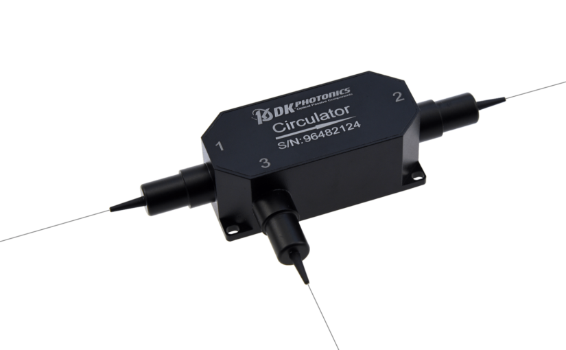
An optical circulator is a high-performance light-wave component that is designed to route the incoming light signals from Port 1 to Port 2 and the incoming light signals from Port 2 to Port 3. In short, it is designed such that the light coming from one port exits from the next port. While some circulators are three-port devices, there are also four-port circulators.

What is an optical isolator?

Also known as an optical diode, an optical isolator is an optical passive component that allows the light to travel in only one direction. Its main component is the Faraday rotator which ensures non-reciprocal rotation while maintaining linear polarization.

The polarization rotation caused by the Faraday rotator always remains in the same relative direction. It means that the rotation is positive 45 degrees in the forward direction and negative 45 degrees in the reverse direction. It happens because of the change in the relative magnetic field direction, positive one way, and negative the other way. Hence, it adds to the total of 90 degrees when light travels in the forward direction and then the same in the backward direction. This is what makes it possible to achieve higher isolation. 

What is an optical rotator?

An optical rotator is typically an in-line Faraday rotator that is designed to rotate the polarization of the input light by 45 degrees. This rotator is used for amplitude modulation of light and is an integral part of optical isolators and optical circulators.

Circulators vs. Isolators vs. Rotators

Difference between an Optical Circulator & Isolator & Rotator

An optical circulator is used to route the incoming light signals from port 1 to port 2 in a way that if some of the emitted light is reflected back to the circulator, it doesn’t exit from port 1 but from port 3. Thus, it wouldn’t be wrong to say that its function is analogous to electronic circulators.

In other words, fiber optic circulators are highly desirable where there is a need to separate optical signals that travel in opposite directions in an optical fiber.

On the contrary, an optical isolator is widely used in all those fiber optic applications where there is a need to prevent unwanted feedback into an optical oscillator, such as a laser cavity.

On the other hand,the main purpose of using an optical rotator is to achieve higher isolation, low insertion loss, high extinction ratio, and high return loss in optical devices such as optical circulators and isolators. As mentioned, they also help ensure non-reciprocal rotation while maintaining linear polarization.

DK Photonics is the leading China-based manufacturer of optical passive components, including regular and high-power optical circulators, isolators, & rotators. If you need optical passive components for your projects and want some guidance, please feel free to connect with us. 

Essential Things to Know About Optical Circulators

In sophisticated optical communication systems, the optical circulator has become one of the most critical components. It’s used to split optical signals in an optical cable that is traveling in different directions.

Optical circulators have been widely used in a variety of disciplines, including telecommunications, medicine, and imaging. We’ll learn more about the optical circulator in this article.

What Is an Optical Circulator?

An optical circulator is a device that allows light to travel from one optical cable to the next. It’s a non-reciprocal device that routes light dependent on the propagation direction. Light can be moved forward using both an optical circulator and an optical isolator. In contrast to the optical circulator, the optical isolator often loses more light energy.

Optical circulators typically have three ports, two of which are utilized as input ports and one as an output port. A signal is sent from port 1 to port 2, followed by another signal from port 2 to port 3. Lastly, the third signal can be sent from port 3 to port 1. Because many applications only need two, they can be designed to prevent any light that enters the third port.

Optical Circulator Components Technologies

The following components make up an optical circulator:

Faraday Rotator

Faraday rotators use the Faraday effect, which is the rotation of the polarization plane of electromagnetic waves in a material subjected to a magnetic field parallel to the wave’s propagation direction.

Birefringent Crystal (Birefringent Crystal):

The polarization state of the light beam and the relative orientation of the crystal affect light propagation in the birefringent crystal. The beam’s polarization can be adjusted, or the beam can be split into two orthogonal polarization states.

Beam Displacer and Waveplate

Birefringent crystals come in two varieties: waveplate and beam displacer. A waveplate is formed by cutting a birefringent crystal to a particular orientation in which the crystal’s optic axis is parallel to the crystal border and in the incident plane. An entering beam is separated into two beams with orthogonal polarization states using a beam displacer.

Optical Circulator Classifications

According to the concept of polarization:

Polarization-dependent optical circulators and polarization-independent optical circulators are two types of optical circulators. The former is employed for light with a specific polarization state, whereas the latter is not limited to a light’s polarization state.

The vast majority of optical circulators used in fiber optic communications are polarization-independent.

In terms of functionality:

There are two types of optical circulators: full circulator and quasi-circulator. In a complete cycle, a full circulator makes use of all ports. Light travels from port 1 to port 2, then from port 2 to port 3, and finally from port 3 to port 1.

Light travels through all ports sequentially in a quasi-circulator, but the light from the last port is lost and cannot be sent back to the first port. A quasi-circulator is sufficient for most purposes.

Conclusion

You may now have a general idea of what an optical circulator is. Using an optical circulator to route light signals with minimal loss is a cost-effective and efficient approach.

Introduction of Fiber Optic Coupler with its Benefits & Classification

A fiber optic coupler is an indispensable part of the world of electrical devices. Without these no signals would be transmitted or converted from inputs to outputs. This is the reason these are so important thereby this article discussed about these, introduction, classification and benefits in detail.

Fiber Optic Coupler is an optical cog that is capable of connecting single or multiple fiber ends in order to permit the broadcast of light waves in manifold paths. This optical device is also capable of coalescing two or more inputs into a single output while dividing a single input into two or more outputs. In comparison to a connector or a splice, the signals may be even more attenuated by FOC i.e. Fiber Optic Couplers; this is due to the division of input signal amongst the output ports.

Types of Fiber Optic Coupler

Fiber Optic Couplers are broadly classified into two, the active or passive devices. For the operation of active fiber coupler an external power source is required, conversely no power is needed when it comes to operate the passive fiber optic couplers.

Fiber Optic Couplers can be of different types for instance X couplers, PM Fiber Couplers, combiners, stars, splitters and trees etc. Let’s discuss the function of each of the type of the Fiber Optic Couplers:

Combiners: This type of Fiber Optic Coupler combines two signals and yields single output.

Splitters: These supply multiple (two) outputs by using the single optical signal. The splitters can be categorized into T couplers and Y couplers, with the former having an irregular power distribution and latter with equal power allocation.

Tree Couplers: The Tree couplers execute both the functions of combiners as well as splitters in just one device. This categorization is typically based upon the number of inputs and outputs ports. These are either single input with a multi-output or multi-input with a single output.

PM Coupler: This stands for Polarization Maintaining Fiber Coupler. It is a device which either coalesces the luminosity signals from two PM fibers into a one PM fiber, or splits the light rays from the input PM fiber into multiple output PM fibers. Its applications include PM fiber interferometers, signal monitoring in its systems, and also power sharing in polarization sensitive systems etc.

Star Coupler: The role of star coupler is to distribute power from the inputs to the outputs.

Benefits of Fiber Optical Couplers

There are several benefits of using fiber optic couplers. Such as:

  • Low excess loss,
  • High reliability,
  • High stability,
  • Dual operating window,
  • Low polarization dependent loss,
  • High directivity and Stumpy insertion loss.

The listed benefits of Fiber Optical Couplers make them ideal for many applications for instance community antenna networks, optical communication systems and fiber-to-home technology etc.

2015-Fiber Optic Communication Collimators Market Forecast

Fiber optic collimator lens arrays are forecast with strong value-based growth rates of more than 30% per year (2014-2019)…

Aptos, CA (USA) – March 23, 2015 — ElectroniCast Consultants, a leading market research & technology forecast consultancy addressing the fiber optics communications industry, today announced the release of a new market forecast of the global market consumption and technology trends of small beam collimating lens assemblies in fiber optic communication (including telecommunication, datacom and cable TV) passive and active/integrated (hybrid) components/devices.

The market study covers single lens assemblies, 2-12 lens arrays, and arrays with more than 12 lenses. Both of the lens array categories are forecast with strong growth rates of more than 30% per year (2014-2019). Single lens fiber optic collimator assemblies held the global market share lead, with over 80% in 2014.

“Collimator lenses are used in a variety of photonic products; however this market study forecasts the use of micro-sized collimator lens assemblies, which are used specifically in optical communication components/devices(such as 8CH LGX CWDM Module). Fiber optic collimator lens assemblies serve as a key indicator of the growth of the fiber optic communication component industry,” said Stephen Montgomery, Director of the Fiber Optic Component group at the California-based consultancy.

ElectroniCast defines lens assemblies as “loose” lenses (one or more), which are attached to an optical fiber or fitted/attached into (or on) a planar waveguide/array substrates or other device(s), such as a ferrule, for the purpose of collimating light for optical fiber communication.

The global consumption of fiber optic collimator lens assemblies, which are used in commercial optical communication applications, reached $287.2 million in 2014, an increase of 8.7% over the previous year.

Consumption is based on the geographical (region) location where the lens assembly is first used into (the) higher-level component or module package; therefore, ElectroniCast forecasts that the Asia Pacific Region will hold the market share lead for most of the timeframe covered in the forecast period.  America, led by the United States, is forecast to remain in the 2nd-place market position until 2019.  Europe is forecast to maintain moderate-to-strong growth, as the region is steadily involved in value-added building (and use) of sub-assemblies and equipment.  Market forecast data in the ElectroniCast report refers to consumption (use) for a particular calendar year; therefore, this data is not cumulative data.

DK Photonicswww.dkphotonics.com  specializes in designing and manufacturing of high quality optical passive components mainly for telecommunication, fiber sensor and fiber laser applications,such as 1064nm High Power Isolator,1064nm Components, PM Components, (2+1)x1 Pump Combiner,Pump Laser Protector,Mini-size CWDM,100GHz DWDM,Optical Circulator,PM Circulator,PM Isolator,Fused Coupler,Mini Size Fused WDM.

The Asia Pacific region is the leader in value of the fiber optic communication collimators market; however, the American region is forecast to take the lead in 2019 …

fiber optic collimator

Introduction of the Transients in Optical WDM Networks

A systems analysis continues to be completed to consider dynamical transient effects in the physical layer of an Optical WDM Network. The physical layer dynamics include effects on different time scales. Dynamics from the transmission signal impulses possess a scale of picoseconds. The timing recovery loops in the receivers be employed in the nanoseconds time scale. Optical packet switching in the future networks will have microsecond time scale. Growth and development of such optical networks is yet continuing. Most of the advanced development work in optical WDM networks is presently focused on circuit switching networks, where lightpath change events (for example wavelength add/drop or cross-connect configuration changes) happen on the time scale of seconds.

It is focused on the dynamics from the average transmission power associated with the gain dynamics in Optical Line Amplifiers (OLA). These dynamics may be triggered by the circuit switching events and have millisecond time scale primarily defined by the Amplified Spontaneous Emission (ASE) kinetics in Erbium-Doped Fiber Amplifiers (EDFAs). The transmission power dynamics will also be influenced by other active components of optical network, for example automatically tunable 100GHz DWDM, spectral power equalizers, or other light processing components. When it comes to these dynamics, a typical power of the lightpath transmission signal is recognized as. High bandwidth modulation from the signal, which actually consists of separate information carrying pulses, is mostly ignored.

14_nodes Ring WDMRing WDM networks implementing communication between two fixed points are very well established technology, in particular, for carrying SONET over the WDM. Such simple networks with fixed WDM lighpaths happen to be analyzed in many detail. Fairly detailed first principle models for transmission power dynamics exist for such networks. These models are implemented in industrial software allowing engineering design calculations and dynamical simulation of these networks. Such models could possibly have very high fidelity, but their setup, tuning (model parameter identification) and exhaustive simulations covering a variety of transmission regimes are potentially very labor intensive. Adding description of new network components to such model could need a major effort.

14_nodes Mesh WDMThe problems with detailed first principle models is going to be greatly exacerbated for future Mesh WDM networks. The near future core optical networks will be transparent to wavelength signals on a physical layer. In such network, each wavelength signal travels through the optical core between electronic IP routers around the optical network edge using the information contents unchanged. The signal power is attenuated in the passive network elements and boosted by the optical amplifiers. The lightpaths is going to be dynamically provisioned by Optical Cross-Connects (OXCs), routers, or switches independently on the underlying protocol for data transmission. Such network is basically a circuit switched network. It might experience complex transient processes of the average transmission power for every wavelength signal at the event of the lightpath add, drop, or re-routing. A mix of the signal propagation delay and channel cross-coupling might result in the transmission power disturbances propagating across the network in closed loops and causing stamina oscillations. Such oscillations were observed experimentally. Additionally, the transmission power and amplifier gain transients could be excited by changes in the average signal power because of the network traffic burstliness. If for some period of time the wavelength channel bandwidth is not fully utilized, this could result in a loss of the average power (average temporal density of the transmitted information pulses).

First circuit switched optical networks are already being designed and deployed. Fraxel treatments develops rapidly for metro area and long term networks. Engineering design of circuit switched networks is complicated because performance has to be guaranteed for all possible combinations of the lightpaths. Further, as such networks develop and grow, they potentially need to combine heterogenous equipment from a variety of vendors. A system integrator (e.g., DK Photonics) of such network might be different from subsystems or component manufacturer. This creates a necessity of developing adequate means of transmission power dynamics calculations which are suitable for the circuit switched network business. Ideally, these methods should be modular, independent on the network complexity, and use specifications on the component/subsystem level.

DK Photonics has technical approach to systems analysis that’s to linearize the nonlinear system around a fixed regime, describe the nonlinearity like a model uncertainty, and apply robust analysis that guarantees stability and gratifaction conditions within the presence of the uncertainty. For a user of the approach, there is no need to understand the derivation and system analysis technicalities. The obtained results are very simple and relate performance to basic specifications of the network components. These specifications are somewhat not the same as those widely used in the industry, but could be defined from simple experimentation using the components and subsystems. The obtained specification requirements may be used in growth and development of optical amplifiers, equalizers, optical attenuators, other transmission signal conditioning devices, OADM Modules, OXCs, and any other optical network devices and subsystems influencing the transmission power.

DK Photonics – www.dkphotonics.com  specializes in designing and manufacturing of high quality optical passive components mainly for telecommunication, fiber sensor and fiber laser applications,such as WDM, FWDM, CWDM, DWDM, OADM,Optical Circulator, Isolator, PM Circulator, PM Isolator, Fused Coupler, Fused WDM, Collimator, Optical Switch and Polarization Maintaining Components, Pump Combiner, High power isolator, Patch Cord and all kinds of connectors.

Testing Fiber Optic Splitters Or Other Passive Devices

A fiber optic splitter is a device that splits the fiber optic light into several parts by a certain ratio. For example, when a beam of fiber optic light transmitted from a 1X4 equal ratio splitter, it will be divided into 4-fiber optic light by equal ratio that is each beam is 1/4 or 25% of the original source one. A Optical Splitter is different from WDM. WDM can divide the different wavelength fiber optic light into different channels. fiber optic splitter divide the light power and send it to different channels.

Most Splitters available in 900µm loose tube and 250µm bare fiber. 1×2 and 2×2 couplers come standard with a protective metal sleeve to cover the split. Higher output counts are built with a box to protect the splitting components.

Testing a coupler or splitter (both names are used for the same device) or other passive fiber optic devices like switches is little different from testing a patchcord or cable plant using the two industry standard tests, OFSTP-14 for double-ended loss (connectors on both ends) or FOTP-171 for single-ended testing.

First we should define what these passive devices are. An optical coupler is a passive device that can split or combine signals in optical fibers. They are named by the number of inputs and outputs, so a splitter with one input and 2 outputs is a 1×2 fiber splitter, and a PON splitter with one input and 32 outputs is 1×32 splitter. Some PON splitters have two inputs so it would be a 2X32. Here is a table of typical losses for splitters.

Splitter-Ratio

Important Note! Mode Conditioning can be very important to testing couplers. Some of the ways they are manufactured make them very sensitive to mode conditioning, especially multimode but even singlemode couplers. Singlemode couplers should always be tested with a small loop in the launch cable (tied down so it does not change and set the 0dB reference with the loop.) Multimode couplers should be mode conditioned by a mandrel wrap or similar to ensure consistency.

Let’s start with the simplest type. Shown below is a simple 1X2 splitter with one input and two outputs. Basically, in one direction it splits the signal into 2 parts to couple to two fibers. If the split is equal, each fiber will carry a signal that is 3dB less than the input (3dB being a factor of two) plus some excess loss in the coupler and perhaps the connectors on the splitter module. Going the other direction, signals in either fiber will be combined into the one fiber on the other side. The loss is this direction is a function of how the coupler is made. Some couplers are made by twisting two fibers together and fusing them in high heat, so the coupler is really a 2X2 coupler in which case the loss is the same (3dB plus excess loss) in either direction. Some splitters use optical integrated components, so they can be true splitters and the loss in each direction may different.

optical coupler

So for this simple 1X2 splitter, how do we test it? Simply follow the same directions for a double-ended loss test. Attach a launch reference cable to the test source of the proper wavelength (some splitters are wavelength dependent), calibrate the output of the launch cable with the meter to set the 0dB reference, attach to the source launch to the splitter, attach a receive launch cable to the output and the meter and measure loss. What you are measuring is the loss of the splitter due to the split ratio, excess loss from the manufacturing process used to make the splitter and the input and output connectors. So the loss you measure is the loss you can expect when you plug the splitter into a cable plant.

To test the loss to the second port, simply move the receive cable to the other port and read the loss from the meter. This same method works with typical PON splitters that are 1 input and 32 outputs. Set the source up on the input and use the meter and reference cable to test each output port in turn.

What about the other direction from all the output ports? (In PON terms, we call that upstream and the other way from the 1 to 32 ports direction downstream.) Simply reverse the direction of the test. If you are tesing a 1X2 splitter, there is just one other port to test, but with a 1X32, you have to move the source 32 times and record the results on the meter.

fiber-splitter

What about multiple input and outputs, for example a 2X2 coupler? You would need to test from one input port to the two outputs, then from the other input port to each of the two outputs. This involves a lot of data sometimes but it needs to be tested.

There are other tests that can be performed, including wavelength variations (test at several wavelengths), variations among outputs (compare outputs) and even crosstalk (put a signal on one output and look for signal on other outputs.)

Once installed, the splitter simply becomes one source of loss in the cable plant and is tested as part of that cable plant loss for insertion loss testing. Testing splitters with an OTDR is not the same in each direction.

Other Passive Devices

There are other passive devices that require testing, but the test methods are similar.

Fiber optic switches are devices that can switch an input to one of several outputs under electronic control. Test as you would the splitter as shown above. Switches may be designed for use in only one direction, so check the device specifications to ensure you test in the proper direction. Switches may also need testing for consistency after multiple switch cycles and crosstalk.

Attenuators are used to reduce signal levels at the receiver to prevent overloading the receiver. There is a page on using attenuators that you should read. If you need to test an attenuator alone, not part of a system, use the test for splitters above by using the attenuator to connect the launch and receive cables to see if the loss is as expected.

Wavelength-division multiplexers can be tricky to test because they require sources at a precise wavelenth and spectral width, but otherwise the test procedures are similar to other passive components.

Fiber optic couplers or splitters are available in a wide range of styles and sizes to split or combine light with minimal loss. All couplers are manufactured using a very simple proprietary process that produces reliable, low-cost devices. They are physically rugged and insensitive to operating temperatures. Couplers can be fabricated in custom fiber lengths and/or with terminations of any type.

DK Photonicswww.dkphotonics.com  specializes in designing and manufacturing of high quality optical passive components mainly for telecommunication, fiber sensor and fiber laser applications,such as PLC Splitter, WDM, FWDM, CWDM, DWDM, OADM,Optical Circulator, Isolator, PM Circulator, PM Isolator, Fused Coupler, Fused WDM, Collimator and Polarization Maintaining Components, Pump Combiner, High power isolator, Patch Cord and all kinds of connectors.

DK Photonics:Huawei to invest over $4 billion in fixed broadband technology in 3 years

Telecom network vendor Huawei on Thursday said it will be investing over $4 billion in fixed broadband (FBB) technology research and development over the next three years.

Huawei’s plans to invest significantly in fixed broadband technology reflects a report from Dell’Oro Group that said wireline telecom markets will grow at a CAGR of 3 percent against 1 percent growth for wireless between 2013 and 2018.

In August, Dell’Oro Group said the combined service provider equipment markets will grow at a CAGR of 2 percent between 2013 and 2018 — after recording a CAGR of -1 percent between 2008 and 2013.

Huawei said the $4 billion investment will focus on products and solutions which will support their customers with providing an improved service experience for end users.

Huawei Products and Solutions President Ryan Ding said: “Our investment will further develop technological advances, help customers increase their competitiveness and decrease overall operating costs.”

Existing technologies are changing, next-generation High-Efficiency Video Coding is maturing, 4k panel and content production costs are reducing and the development of the 4k video industry, are all driving new solutions.

Huawei to invest over $4 billion in fixed broadband technology in 3 years

As LTE and 5G deployment continues, construction of high-performance networks which guarantee better customer experience will be expected by telecom operators. Huawei said FBB technologies will be progressed by leveraging big data, data centers and cloud computing to meet their needs.

Tam Dell’Oro, president and founder of Dell’Oro Group, said: “While we believe carriers will continue to enhance their wireless networks, we anticipate carriers will put more emphasis on backhauling traffic which means improving their fixed line networks in the next five years.”

Huawei today said it will innovate Software Defined Networking (SDN), Network Functions Virtualization (NFV) to initiate open broadband networks that help customers simplify operations and management, realize service innovation and improve network efficiency.

For next-generation networks, Huawei will conduct research and develop on new key technologies and architectures for IP and all-optical networks, advancing FBB network development.

Fixed LTE broadband access gains

At present, 1.26 billion households do not have DSL, cable, or fiber-optic broadband. Fixed and mobile telecoms are looking to LTE to make the connection.

“By the end of 2014, there will be 14.5 million residential and commercial premises with fixed LTE broadband access. By 2019, that figure should grow to 123 million,” said Jake Saunders, VP and 4G practice director at ABI Research.

ITU pitches for broadband

ITU, a telecom industry association under the aegis of UN, says more than 40 percent of the world’s people are already online, with the number of Internet users rising from 2.3 billion in 2013 to 2.9 billion by the end of this year.

Over 2.3 billion people will access mobile broadband by end 2014, climbing steeply to a predicted 7.6 billion within the next five years.

ITU says there are now over three times as many mobile broadband connections as there are conventional fixed broadband subscriptions.

Huawei on green telecom

Meanwhile, Eric Xu, Rotating chief executive officer, Huawei, said: “Huawei is committed to socio-economic and environmental sustainability. We leverage our expertise to bridge the digital divide and deliver high-quality digital connectivity for all.”

“We always honor our commitment to supporting secure and stable network operations anytime, anywhere. We contribute to low-carbon economies by helping customers and industries improve productivity and reduce energy consumption,” said Xu at the sixth Global Supplier Sustainability Conference in Shenzhen, China.

DK Photonicswww.dkphotonics.com  specializes in designing and manufacturing of high quality optical passive components mainly for telecommunication, fiber sensor and fiber laser applications,such as PLC Splitter, WDM, FWDM, CWDM, DWDM, OADM,Optical Circulator, Isolator, PM Circulator, PM Isolator, Fused Coupler, Fused WDM, Collimator, Optical Switch and Polarization Maintaining Components, Pump Combiner, High power isolator, Patch Cord and all kinds of connectors.

Fiber Optics Sensors Provide Early Warning for Landslides-DK Photonics

CASERTA, Italy, Sept. 29, 2014 — Fiber optic sensors could warn people of imminent landslides, potentially saving lives and reducing destruction.

A team at the Second University of Naples is developing sensor technology that could detect and monitor both large landslides and slow slope movements. The researchers hope to mitigate the effects of these major natural disasters, similar to the way hurricane tracking can prompt coastal evacuations.

Optical fiber sensors embedded in shallow trenches within slopes would detect small shifts in the soil, the researchers said. Landslides are always preceded by various types of pre-failure strains, they said.

While the magnitude of pre-failure strains depends on the rock or soil involved — ranging from fractured rock debris and pyroclastic flows to fine-grained soils — they are measurable. Electrical sensors have long been used for monitoring landslides, but that type of sensor can be easily damaged, the researchers said. Optical fiber is more robust, economical and sensitive.

“Distributed optical fiber sensors can act as a ‘nervous system’ of slopes by measuring the tensile strain of the soil they’re embedded within,” said professor Dr. Luigi Zeni.

The researchers are also combining several types of optical fiber sensors into a plastic tube that twists and moves under the forces of the pre-failure strains. This will allow them to monitor the movement and bending of the optical fiber remotely to determine if a landslide is imminent.

The use of fiber optic sensors “allows us to overcome some limitations of traditional inclinometers, because fiber-based ones have no moving parts and can withstand larger soil deformations,” Zeni said.

He added that such sensors can be used to cover several square kilometers and monitored continuously to pinpoint critical zones.

The team will present their research at Frontiers in Optics in Tucson, Ariz., next month.


DK Photonicswww.dkphotonics.com  specializes in designing and manufacturing of high quality optical passive components mainly for telecommunication, fiber sensor and fiber laser applications,such as PLC Splitter, WDM, FWDM, CWDM, DWDM, OADM,Optical Circulator, Isolator, PM Circulator, PM Isolator, Fused Coupler, Fused WDM, Collimator, Optical Switch and Polarization Maintaining Components, Pump Combiner, High power isolator, Patch Cord and all kinds of connectors.

Fiber Optic Connector Market Forecast-DK Photonics

According to ElectroniCast, multifiber / multichannel fiber optic connectors are set for explosive growth, led by MXC™ fiber connectors with triple-digit increases through 2018…

Aptos, CA (USA) – September 22, 2014 —ElectroniCast Consultants, a leading market & technology forecast consultancy addressing the fiber optics communications industry, today announced the release of their annual market forecast and analysis of the use offiber optic connectors and mechanical splices in communication applications.

FC fiber optic connector

According to ElectroniCast, the worldwide fiber optic connector/mechanical splice consumption value reached $2.63 billion in 2013.  Multimode fiber optic connectors led the consumption value in 2013 with a 64 percent market share.  The use of multimode fiber optic connectors is forecast to increase at a rate of 14 percent per year, from $1.68 billion in 2013 to $3.24 billion in 2018.

“The multimode LC small form factor connector is forecast to maintain the leadership position in relative market share throughout the forecast period, as well as increasing at an average annual rate of 20 percent,” said Stephen Montgomery, Director of the Fiber Optic Component group at ElectroniCast.

The fastest annual growth is set to come from the use of multifiber/multichannel fiber optic connectors are set for explosive growth, led by MXC™ fiber connectors with triple-digit increases through 2018.  The newly-release connector design enables more fibers (up to 64 fibers at 25G) to be accommodated in fast-paced server/storage data center and other applications.  Both the single-mode and the multimode MXC fiber optic connectors are forecast to reach strong values by 2018.

Other new fiber optic connector designs, besides the MXC connector, are planned for deployment to address the high-density/high-speed data speeds of 25Gbps or greater in the next couple of years.

“Field-installable connectors for indoor and outdoor use are increasing in demand and thus are making a big-splash in the overall connector product lines of several competitors.  Fiber optic connector-types, such as SC, ST, LC, FC and even the MPO and other possibilities are finding their way to the marketplace.  Both mechanical-splice and fusion-splice technologies are meeting the requirements in the field-installable fiber optic product availability,” Montgomery added.

The global fiber optic connector/mechanical splice consumption is driven by a dramatic increase in bandwidth demand beyond the limits of copper.  As optical fiber use migrates closer and closer to the end user, where cable lengths are shorter with higher fiber counts, the requirements for jointing fibers becomes more critical. Splicing and connecting, play a significant role in a network’s cost and performance.

There are over 140 vendors competing for the global fiber optic connector/ mechanical splice market, which ElectroniCast tracks in a product matrix showing participation in the following: connectors, cable assemblies, optical backplanes, and fiber optic installation apparatus; however, is dominated by a few companies that have a broad base in various interconnect products.

DK Photonicswww.dkphotonics.com specializes in designing and manufacturing of high quality optical passive components mainly for telecommunication, fiber sensor and fiber laser applications,such as WDM, FWDM, CWDM, DWDM, OADM,Optical Circulator, Isolator, PM Circulator, PM Isolator, Fused Coupler, Fused WDM, Collimator, Optical Switch and Polarization Maintaining Components, Pump Combiner, High power isolator, Patch Cord and all kinds of connectors.

Differences Between FBT Coupler and PLC splitters

Optical networks require signal being splitted somewhere in design to serve for multiple customers. Splitter technology has made a huge step forward in the past few years by introducing PLC (Planar Lightwave Circuit) splitter. It has proven itself as a higher reliable type of device compared to the traditional FBT (Fused Biconical Taper) splitter. While being similar in size and outer appearance, both types of splitters provide data and video access for business and private customers. However, internally the technologies behind these types vary, thus giving  service providers a possibility to choose a more appropriate solution.

FBT splitter is made out of materials that are easily available, for example steel, fiber, hot dorm and others. All of these materials are low-price, which determines the low cost of the device itself. The technology of the device manufacturing is relatively simple, which has the impact on its price as well. In scenario where multiple splits are needed, the size of the device may become an issue. It is important to keep in mind that splitters are being deployed in the fields either in cabinets or in strand mountings, so the size of device plays a critical role. FBT splitters only support three wavelengths (850/1310/1550 nm) which makes these devices unable to operate on other wavelengths. Inability of adjusting wavelengths makes FBT splitters less customizable for different purposes. Moreover, the devices are to a high extent temperature sensitive, providing a stable working range of -5 to 75 C. In certain areas, such as Scandinavian countries this temperature restrictions may be crucial. The signal processed by FBT splitters cannot be splitted evenly due to lack of management of the signals

PLC splitter manufacturing technology is more complex. It uses semiconductor technology (lithography, etching, developer technology) production, hence it is more difficult to manufacture. Therefore, the price of the device is higher. However, there is a number of advantages the device possesses. The size of the device is compact, compared to FBT splitters, making it suitable for density applications. PLC splitter operates at wider temperature range (-40 to 85 C), allowing its deploying in the areas of extreme climate. The split ratio goes up to 64, providing a high reliability. Furthermore, the signal can be split equally due to technology implemented. A range of wavelengths (1260 – 1650 nm) is provided, so the wavelengths are adjustable. Critical points of the device that might fail are input and output, so the general risk of failure is low.

Differences Between FBT and PLC splitters

 Table 1. FBT and PLC splitter feature comparison

DK Photonicswww.dkphotonics.com  specializes in designing and manufacturing of high quality optical passive components mainly for telecommunication, fiber sensor and fiber laser applications,such as PLC Splitter, WDM, FWDM, CWDM, DWDM, OADM,Optical Circulator, Isolator, PM Circulator, PM Isolator, Fused Coupler, Fused WDM, Collimator, Optical Switch and Polarization Maintaining Components, Pump Combiner, High power isolator, Patch Cord and all kinds of connectors.