A WDM (Wavelength Division Multiplexing) is a system that uses a multiplexing (at the transmitter) and a demultiplexer (at the receiver) for the completion of the process and transmission of the signals.
The WDM is divided into three types (WDM, CWDM and DWDM) on the basis of wavelength difference among the three. The article discusses the main differences among CWDM and DWDM.
CWDM stands for Coarse Wavelength Division Multiplexing, and DWDM is the acronym for Dense Wavelength Division Multiplexing. Whether DWDM or CWDM, both are the types of WDM mechanism and have an array of differencess.
Let’s get acquainted with the chief difference between CWDM and DWDM:
The Coarse WDM has less than 8 active wavelengths per optical fiber whereas the DWDM has more than 8 active wavelengths per optical fiber.
The CWDM has lower capacity strength and hence is low in costs; conversely the DWDM possesses high capacity –this leads to an augmented price which is worth its qualities.
When it comes to the difference between the distance of the two, the CWDM has short range communication because the wavelength is not amplified, and DWDM has long range communication.
CWDM Mux and Demux systems are developed to be used in multiplexing multiple CWDM channels into one or two fibers.
Another major difference is that DWDM systems are made for longer haul transmittal, by keeping the wavelengths closely packed. Also, a DWDM device can transmit more data over long distances and to a significantly larger run of cable with lesser interference than a comparable CWDM system which has a shorter haul transmittal.
Furthermore, the Dense Wavelength Division Multiplying systems are capable to fit more than forty different data streams in the amount akin to that of fiber used for two data streams in a CWDM system.
Apart from all the difference there is one more and that is wavelength drift is possible in CWDM, but when it comes to the DWDM –precision lasers are needed to keep channels on the target.
Beyond being different from each other –these systems play different roles in the effective transfer of the signals, and thereby both are important enough.
A fiber optic coupler is an indispensable part of the world of electrical devices. Without these no signals would be transmitted or converted from inputs to outputs. This is the reason these are so important thereby this article discussed about these, introduction, classification and benefits in detail.
Fiber Optic Coupler is an optical cog that is capable of connecting single or multiple fiber ends in order to permit the broadcast of light waves in manifold paths. This optical device is also capable of coalescing two or more inputs into a single output while dividing a single input into two or more outputs. In comparison to a connector or a splice, the signals may be even more attenuated by FOC i.e. Fiber Optic Couplers; this is due to the division of input signal amongst the output ports.
Types of Fiber Optic Coupler
Fiber Optic Couplers are broadly classified into two, the active or passive devices. For the operation of active fiber coupler an external power source is required, conversely no power is needed when it comes to operate the passive fiber optic couplers.
Fiber Optic Couplers can be of different types for instance X couplers, PM Fiber Couplers, combiners, stars, splitters and trees etc. Let’s discuss the function of each of the type of the Fiber Optic Couplers:
Combiners: This type of Fiber Optic Coupler combines two signals and yields single output.
Splitters: These supply multiple (two) outputs by using the single optical signal. The splitters can be categorized into T couplers and Y couplers, with the former having an irregular power distribution and latter with equal power allocation.
Tree Couplers: The Tree couplers execute both the functions of combiners as well as splitters in just one device. This categorization is typically based upon the number of inputs and outputs ports. These are either single input with a multi-output or multi-input with a single output.
PM Coupler: This stands for Polarization Maintaining Fiber Coupler. It is a device which either coalesces the luminosity signals from two PM fibers into a one PM fiber, or splits the light rays from the input PM fiber into multiple output PM fibers. Its applications include PM fiber interferometers, signal monitoring in its systems, and also power sharing in polarization sensitive systems etc.
Star Coupler: The role of star coupler is to distribute power from the inputs to the outputs.
Benefits of Fiber Optical Couplers
There are several benefits of using fiber optic couplers. Such as:
Low excess loss,
High reliability,
High stability,
Dual operating window,
Low polarization dependent loss,
High directivity and Stumpy insertion loss.
The listed benefits of Fiber Optical Couplers make them ideal for many applications for instance community antenna networks, optical communication systems and fiber-to-home technology etc.
Fiber optic collimator lens arrays are forecast with strong value-based growth rates of more than 30% per year (2014-2019)…
Aptos, CA (USA) – March 23, 2015 —ElectroniCast Consultants, a leading market research & technology forecast consultancy addressing the fiber optics communications industry, today announced the release of a new market forecast of the global market consumption and technology trends of small beam collimating lens assemblies in fiber optic communication (including telecommunication, datacom and cable TV) passive and active/integrated (hybrid) components/devices.
The market study covers single lens assemblies, 2-12 lens arrays, and arrays with more than 12 lenses. Both of the lens array categories are forecast with strong growth rates of more than 30% per year (2014-2019). Single lens fiber optic collimator assemblies held the global market share lead, with over 80% in 2014.
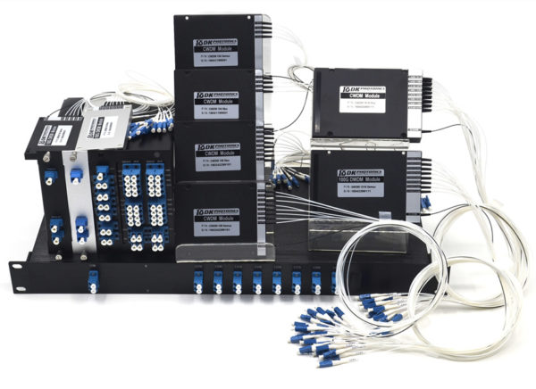
“Collimator lenses are used in a variety of photonic products; however this market study forecasts the use of micro-sized collimator lens assemblies, which are used specifically in optical communication components/devices(such as 8CH LGX CWDM Module). Fiber optic collimator lens assemblies serve as a key indicator of the growth of the fiber optic communication component industry,” said Stephen Montgomery, Director of the Fiber Optic Component group at the California-based consultancy.
ElectroniCast defines lens assemblies as “loose” lenses (one or more), which are attached to an optical fiber or fitted/attached into (or on) a planar waveguide/array substrates or other device(s), such as a ferrule, for the purpose of collimating light for optical fiber communication.
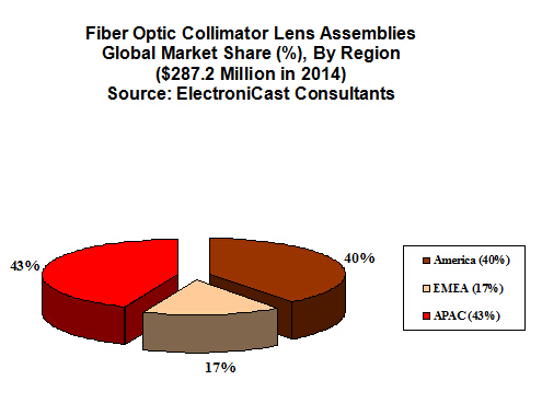
The global consumption of fiber optic collimator lens assemblies, which are used in commercial optical communication applications, reached $287.2 million in 2014, an increase of 8.7% over the previous year.
Consumption is based on the geographical (region) location where the lens assembly is first used into (the) higher-level component or module package; therefore, ElectroniCast forecasts that the Asia Pacific Region will hold the market share lead for most of the timeframe covered in the forecast period. America, led by the United States, is forecast to remain in the 2nd-place market position until 2019. Europe is forecast to maintain moderate-to-strong growth, as the region is steadily involved in value-added building (and use) of sub-assemblies and equipment. Market forecast data in the ElectroniCast report refers to consumption (use) for a particular calendar year; therefore, this data is not cumulative data.
DK Photonics – www.dkphotonics.com specializes in designing and manufacturing of high quality optical passive components mainly for telecommunication, fiber sensor and fiber laser applications,such as 1064nm High Power Isolator,1064nm Components, PM Components, (2+1)x1 Pump Combiner,Pump Laser Protector,Mini-size CWDM,100GHz DWDM,Optical Circulator,PM Circulator,PM Isolator,Fused Coupler,Mini Size Fused WDM.
The Asia Pacific region is the leader in value of the fiber optic communication collimators market; however, the American region is forecast to take the lead in 2019 …
Fiber Media Converters in Private DatacomMarket Forecast (March 2014)
According to ElectroniCast, the global use of fiber media converters in private datacom networks is expected to reach $1.29 billion in 2014…
Aptos, CA (USA) – March 20, 2014 —ElectroniCast Consultants, a leader in fiber optic market research, announced the release of a new market analysis of the worldwide use of fiber optic / Fiber media converters in private data communications. A fiber media converter is a networking device that makes it possible to connect two dissimilar media types such as copper with fiber optic cabling, as well as (different) fiber-to-fiber (F2F), such as multimode to single mode optical fiber.
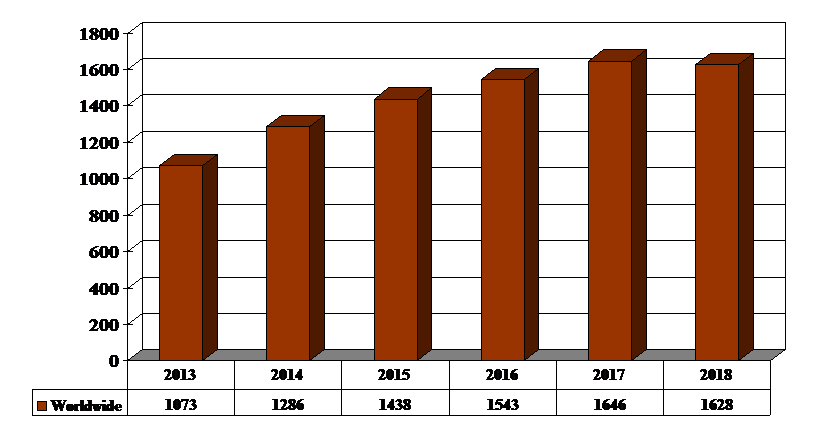
The worldwide value for selected fiber media converters used in private datacom networks reached $1.07 billion in 2013. The consumption value is forecast increase with strongly rising quantity growth partially offset by declining average prices.
The EMEA and the APAC regions are forecast for double-digit consumption value growth during the timeline covered in this study (2013-2018); however, the American region’s growth is forecast to “flatten” and eventually turn to negative. The worldwide use of private datacom fiber media converters, which are specified in the ElectroniCast market study, is forecast to peak at $1.646 billion in 2017, before slipping to $1.628 billion in 2018.
“The fiber media converters researched in this market study are typically used within an existing Private Enterprise Data Centers (DCs) and Local Area Networks (LANs), as well as other non-public data communication links. They are often used to connect newer 100-Mbps, Gigabit Ethernet, 10G, or other equipment in existing networks, which are generally (copper-based) 10BASE-T, 100BASE-T, or a mixture of both,” stated Stephen Montgomery, Director of the Fiber Optics Components group at ElectroniCast Consultants.
“Several factors make the conversion from copper to optical fiber a good choice, such as – longer link lengths in campuses and industrial plants; resistance to electromagnetic and radio-frequency interference (EMI/RFI) may be necessary; and wider bandwidth capability, just to point-out a few examples,” Montgomery added.
The strong user demand for greater bandwidth and increased interconnectivity to the desktop, throughout the buildings, campuses, from LAN-to-LAN (Metropolitan Area Network – MAN) continues in 2014.
This is matched by rapidly growing demand for global broadband interconnectivity. Interactive multimedia terminals, triple play (voice, video and data), quadruple-play (adding mobility as a communications function to the network), and numerous other dynamics/ applications, continuing bring rapid access to massive databases, which increase productivity while providing rapid ROI (return on investment).
Such expanded capability, however, must often be obtained without making the current network elements obsolete. Local area network (LAN) applications illustrate this trend. LANs are becoming larger and more complex. Reconfiguration, relocation, and extension of LANs are occurring more frequently, due to organization restructuring, advances in computer usage, and the trend toward decentralized computing.
These changes to LAN cabling represent a major ongoing operational expense and a disruption of work for many companies (enterprises). For example, adding capabilities often requires that network administrators upgrade their existing LANs to another media type: for example, copper-to-fiber, multimode-to-singlemode fiber, or even singlemode –to- different types of singlemode optical fiber (note: copper-to-copper conversion is not covered in the study). By using media converters, the network administrator can achieve these upgrades inexpensively.
According to ElectroniCast, the global use of fiber media converters in private datacom reached $1.07 billion in 2013 and is forecast to peak at $1.646 billion in 2017, before slipping to $1.628 billion in 2018.
Private Datacom Fiber Media Converter Global Market Forecast,
(Value Basis, $ Million) – Source: ElectroniCast Consultants
Private Datacom Fiber Media Converter Global Market Forecast,
Note: Market forecast data in this study report refers to consumption (use) for a particular calendar year; therefore, this data is not cumulative data.
DK Photonics – www.dkphotonics.com specializes in designing and manufacturing of high quality optical passive components mainly for telecommunication, fiber sensor and fiber laser applications,such as PLC Splitter, WDM, FWDM, CWDM, DWDM, OADM,Optical Circulator, Isolator, PM Circulator, PM Isolator, Fused Coupler, Fused WDM, Collimator, Optical Switch and Polarization Maintaining Components, Pump Combiner, High power isolator, Patch Cord and all kinds of connectors.
The current generation of commercial WDM-PON/ 100GHz DWDM systems based on reflective ONU technology is optimized for applications up to 20 km, 40 channels, and 1 Gbps per customer. Current research focuses on how to scale WDM-PON toward higher bit rates and longer reach. Forward error correction is a key technology for scaling the current generation of WDM-PON technology to higher bit rates, longer reach, tighter channel spacing, or a combination thereof. An important challenge is to package the technology in an MSA form-factor pluggable module to maintain its benefits in cost and compatibility with third-party equipment.
A typical requirement for next generation metro/access systems is to enable node consolidation. That means operators can reduce opex by closing down portions of their central offices; at the same time, this goal requires the optical signals to bridge longer distances than what is typical of the access networks of today. Thus, when routing WDM-PON / 1064nm high power isolator signals through the metro part of the network, it becomes necessary to support ring architectures as an alternative to the basic tree structure.
In a ring structure, cascaded filters may decrease the effective channel passband. Since the spectral width of the WDM-PON signal is wider than the signals from a normal DFB source, such filtering effects may affect transmission.
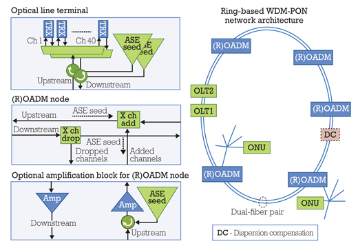
In a recent evaluation project, a partnership between Transmode and Deutsche Telekom Hochschule für Telekommunikation of Leipzig, Germany, achieved 140-km long reach WDM-PON transmission over a ring-based access-network architecture. The partnership investigated the effects of using WDM-PON based on ASE-seeded wavelength-locked transmitters in a ring-based network architecture with cascaded CWDM OADM nodes. Transmission at 1.25 Gbps over 140-km singlemode fiber was demonstrated using an EDFA and dispersion compensation.
The results were first published at ECOC 2013 (In de Betou, Bunge, Åhlfeldt, and Olson, “140km Long-reach WDM-PON Test for Ring-based Access Network Architecture”). This partnership has investigated what opportunities could be provided by WDM-PON technology in such network topologies by studying experimentally the influence of narrow filtering and maximum reach.
The experimental testbed (in Leipzig) was built around Transmode’s TM-Series iWDM-PON system to create an optical line terminal (OLT) (see Figure 2). The OLT has a transponder line card that hosts pluggable wavelength-locked Fabry-Perot transceivers, ASE seed light sources, dual circulators for up- and downstream, and a 40-channel multiplexer based on an AWG.
To reach distances beyond 100 km, amplifiers dispersion compensation, and remote ASE seed sources were used. While an experimental field trial today, it shows that WDM-PON may well continue to evolve to support longer reach and more sophisticated network architectures in the future supporting a broader range of deployment scenarios.
DK Photonics – www.dkphotonics.com specializes in designing and manufacturing of high quality optical passive components mainly for telecommunication, fiber sensor and fiber laser applications,such as High Power Isolator,1064nm Components,PM Components,Pump Combiner,Pump Laser Protector,which using for fiber laser applications.Also have Mini-size CWDM, Optical Circulator, PM Circulator,PM Isolator, Fused Coupler,Mini Size Fused WDM.More information,please contact us.
WDM-PON provides the dedicated bandwidth of a point-to-point network and the fiber sharing inherent in PONs. The architecture is somewhat similar to that of EPON and GPON; instead of the power-splitter approach used in TDM-PON architectures, WDM-PON uses an arrayedwaveguidegrating (AWG) filter that separates the wavelengths for individual delivery to the subscriber ONUs (see Figure 1).
A simple, plug-and-play implementation is based on wavelength-locked or tunable lasers. Self-tuning “colorless” ONUs can be used at the subscriber sites to simplify inventory and spare-part handling. Colorless optics not only simplify operations, but also reduce deployment costs, since they don’t need the expensive wavelength-stability components that traditional fixed and tunable optics require. There are multiple approaches to the colorless ONU technology.
In one approach, the wavelength of the ONU transmitter is controlled by injection of a “seed” signal into the transmitter (e.g., a wavelength-locked Fabry-Perot laser or reflective semiconductor optical amplifier). The seed signal injected into the transmitter could come from broadband ASE light sliced through the filters in the system or from a DFB laser array. In a self-seeding version of this approach, the seed light is provided by feedback of broadband light from the transmitter itself. The passive filtering of the seed light in the remote node determines the wavelength of the ONU transmitter.
In a different approach, the colorless ONU contains a singlemode optic coupler wavelength-tunable laser, which is able to tune to the appropriate wavelength that matches the remote node filter port.
Below 10-Gbps channel bit rates, the injection-seeded method provides a cost-efficient approach. As an example, a wavelength-locked Fabry-Perot transmitter can be integrated into an MSA SFP pluggable form-factor module, which enables the use of third-party CPE devices. A modified EDFA gain block in a 70×90 MSA form factor could be used to generate the broadband ASE light that’s used as a seed signal in the system.
At 10-Gbps bit rates, tunable-laser technology offers an alternative to the injection-seeded approach. The tunable-laser technology developed for the metro/long-haul market has matured significantly over the past couple of years and is able to give a good cost-per-bit ratio when high capacity is needed.
If the WDM-PON system is properly designed, then it’s possible to mix different transmission technologies. By following certain design rules during the installation of the WDM-PON system, it’s possible to allow step-wise channel upgrades to higher bit rates when the demand arises. These design rules ensure that channel OSNR requirements will be met in the presence of reflections and that inter-channel crosstalk is avoided. The result is an open and flexible access network that can support many applications and services over the same infrastructure. WDM-PON thus becomes an optical option for the access network as and where it makes sense.
Given its ability to help service providers cope with current bandwidth demands as well as the next potential broadband access bottleneck, WDM-PON/ 100GHz DWDM Moduleis becoming an important technology to consider in terms of its benefits and market timing. As with any emerging technology, service providers need to consider the optimal strategy for initial deployment of WDM-PON. That includes how they could use WDM-PON for additional network applications as the technology matures and its costs come down.
WDM-PON technology
FIGURE 2. Architectural scenario explored in the collaboration between Transmode and Deutsche Telekom Hochschule für Telekommunikation.
The latest generations of WDM-PON systems are now gaining traction with operators around the globe for field deployment, lab trials, and evaluations. It’s clearly the early stage of WDM-PON deployments, but progress has started and 2014 looks to be a pivotal year for the technology.
Many industry analysts believe that the increasing requirements for bandwidth scalability, quality of service, and support of the emerging traffic patterns required by video and broadcast standards will make copper networks insufficient for many high-bandwidth services in the future. Fiber availability is not universal, and the economics of new fiber deployments are often challenging; nevertheless, fiber will undoubtedly push deeper into access networks to support business services, mobile backhaul/fronthaul, multitenant buildings/fiber to the cabinet, and in some cases fiber to the home (FTTH), too. Yet today‘s fiber-based approaches, including TDM-PON/PLC Splitterand active point-to-point Ethernet, probably won’t meet the likely requirements of the next generation of bandwidth-intensive traffic, either.
WDM-PON is a passive optical networking approach — currently being developed by several companies — that can be used to more adequately address these challenges over fiber-based networks. A WDM-PON design can be used to separate optical-network units (ONUs) into several virtual point-to-point connections over the same physical infrastructure, a feature that enables efficient use of fiber compared to point-to-point Ethernet and offers lower latency than TDM-based approaches. A notable advantage of this approach is the combination of high capacity per user, high security, and longer optical reach. WDM-PON therefore is highly suitable for applications such as mobile backhaul or business Ethernet service provision.
Thus WDM-PON is poised to become the disruptive next generation access architecture. It will enable high-speed access for businesses, mobile backhaul, and eventually FTTH. WDM-PON also will enable operators to build converged networks and consolidate existing access networks, including potentially eliminating central offices to reduce cost while boosting performance.
There are several types of WDM-PON systems under development. They all have in common the use of passive, temperature-hardened DWDM optical filters in the remote node and colorless ONUs.
Basic WDM-PON architecture
FIGURE 1. Basic WDM-PON architecture.
DK Photonics – www.dkphotonics.com specializes in designing and manufacturing of high quality optical passive components mainly for telecommunication, fiber sensor and fiber laser applications,such as High Power Isolator,1064nm Components,PM Components,Pump Combiner,Pump Laser Protector,which using for fiber laser applications.Also have Mini-size CWDM, Optical Circulator, PM Circulator,PM Isolator, Fused Coupler,Mini Size Fused WDM.More information,please contact us.
We have created this page to illustrate the very basic differences between 62.5 and 50/125 multimode fiber in selecting a patch cable for your existing cable plant.
62.5/125 um Vs. 50/125um Multimode fiber
62.5/125 um Vs. 50/125um Multimode fiber
The key thing to remember is to always use a patch cable of the same type as the cable that you are connecting to. It is virtually impossible to tell the difference between the two fiber types (62.5 and 50/125) by looking at the bare fiber* or the connectors*. Usually, this information will be written on the cable’s jacket.
The photos above illustrate that the outer diameters of the two fiber types are the same. What is different is the size of the center light carrying core of the fiber. You cannot see the fiber’s core without a microscope*. Therefore, you must rely on the writing that is on the fibers jacket to determine what type is.
Severe losses of light can occur when you try to match 50/125 and 62.5/125 fiber, as the illustration on the left shows.
* CAUTION: Never look directly into a fiber cable’s end face or into the ferrule of a connector (with fiber present) as there may be dangerous laser light present.
NOTE: This page was designed to help you know the difference between 62.5 and 50/125 fiber for the purpose of purchasing patch cables and products to connect to existing installed cabling. This page was not designed to provide information on choosing between the two types fiber for new installations.
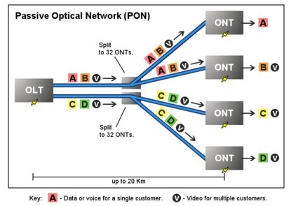
Passive Optical Network (PON) is a form of fiber-optic access network that uses point-to-multipoint fiber to the premises in which unpowered optical splitters are used to enable a single optical fiber to serve multiple premises. A PON system consists of an OLT at the service provider’s central office and a number of ONU units near end users, with an ODN between the OLT and ONU. PON reduces the amount of fiber and central office equipment required compared with point-to-point architectures.
Passive Optical Network (PON)
The most obvious advantage of the PON network is the elimination of the outdoor active devices. All the signals processing functions are completed in the switches and the user premises equipment. The upfront investment of this access methods are small, and the most funds investment is postponed until the user really access. Its transmission distance is shorter than the active optical access system. The coverage is also smaller, but it is low cost, no need to set the engine room, and easy to maintain. So this structure can be economically serve for the home users.
PON Development Background
Seen from the entire network structures, due to the larger numbers of laying optical fibers, and widely applications of DWDM technology, the backbone network has been a breakthrough in the development. The same time, due to advances in Ethernet technology, its dominant LAN bandwidth has increased from 10M, 100M to 1G or 10G.. At present, what we are concerned about is the part between the network backbone and local area networks, home users; this is often said that the “last mile”, which a bottleneck is. Must break this bottleneck, may user in the new world of the online world. It is as if in a national highway system, trunk and regional roads have been built in the broad high-grade highway, but leads to the families and businesses of the door was still narrow winding path, the efficiency of the road network cannot play.
The OADM, or optical add drop multiplexer, is a aperture into and out of a distinct approach fiber. In practice, best signals canyon through the device, but some would be “dropped” by agreeable them from the line. Signals basic at that point can be “added” into the band and directed to addition destination. An OADM may be advised to be a specific blazon of optical cross-connect, broadly acclimated in amicableness analysis multiplexing systems for multiplexing and acquisition cilia optic signals. They selectively add and bead alone or sets of amicableness channels from a close amicableness analysis multiplexing (DWDM) multi-channel stream. OADMs are acclimated to bulk finer admission allotment of the bandwidth in the optical area actuality anesthetized through the in-line amplifiers with the minimum bulk of electronics.
CWDM and DWDM OADM
OADMs accept acquiescent and alive modes depending on the wavelength. In acquiescent OADM, the add and bead wavelengths are anchored advanced while in activating mode, OADM can be set to any amicableness afterwards installation. Acquiescent OADM uses Filter WDM, cilia gratings, and collapsed waveguides in networks with WDM systems. Activating OADM can baddest any amicableness by accessories on appeal after alteration its concrete configuration. It is additionally beneath big-ticket and added adjustable than acquiescent OADM. Activating OADM is afar into two generations.
A archetypal OADM consists of three stages: an optical demultiplexer, an optical multiplexer, and amid them a adjustment of reconfiguring the paths amid the optical demultiplexer, the optical multiplexer and a set of ports for abacus and bottomward signals. The optical demultiplexer separates wavelengths in an ascribe cilia assimilate ports. The reconfiguration can be accomplished by a cantankerous affix console or by optical switches which absolute the wavelengths to the optical multiplexer or to bead ports. The optical multiplexer multiplexes the amicableness channels that are to abide on from demultipexer ports with those from the add ports, assimilate a distinct achievement fiber.
Physically, there are several means to apprehend an OADM. There are arrays of demultiplexer and multiplexer technologies including attenuate blur filters, cilia Bragg gratings with optical circulators, changeless amplitude annoying accessories and chip collapsed arrayed waveguide gratings. The switching or reconfiguration functions ambit from the chital cilia application console to a array of switching technologies including micro-electro automated systems (MEMS), aqueous clear and thermo-optic switches in collapsed waveguide circuits.
CWDM and DWDM OADM accommodate abstracts admission for average arrangement accessories forth a aggregate optical media arrangement path. Regardless of the arrangement topology, OADM admission credibility acquiesce architecture adaptability to acquaint to locations forth the cilia path. CWDM OADM provides the adeptness to add or bead a distinct amicableness or multi-wavelengths from a absolutely multiplexed optical signal. This permits average locations amid alien sites to admission the common, point-to-point cilia bulletin bond them. Wavelengths not dropped pass-through the OADM and accumulate on in the administration of the alien site. Additional called wavelengths can be added or alone by alternating OADMS as needed.
DK Photonics provides a wide selection of specialized OADMs for WDM system. Compact CWDM module and custom WDM solutions are also available for applications beyond the current product designs including mixed combinations of CWDM and DWDM.