Know the Difference between CWDM and DWDM

A WDM (Wavelength Division Multiplexing) is a system that uses a multiplexing (at the transmitter) and a demultiplexer (at the receiver) for the completion of the process and transmission of the signals.

The WDM is divided into three types (WDM, CWDM and DWDM) on the basis of wavelength difference among the three. The article discusses the main differences among CWDM and DWDM.


CWDM stands for Coarse Wavelength Division Multiplexing, and DWDM is the acronym for Dense Wavelength Division Multiplexing. Whether DWDM or CWDM, both are the types of WDM mechanism and have an array of differencess.

Let’s get acquainted with the chief difference between CWDM and DWDM:

  • The Coarse WDM has less than 8 active wavelengths per optical fiber whereas the DWDM has more than 8 active wavelengths per optical fiber.
  • The CWDM has lower capacity strength and hence is low in costs; conversely the DWDM possesses high capacity –this leads to an augmented price which is worth its qualities.
  • When it comes to the difference between the distance of the two, the CWDM has short range communication because the wavelength is not amplified, and DWDM has long range communication.
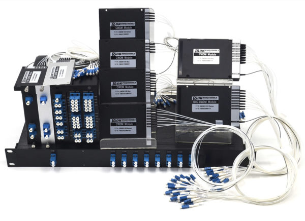
  • CWDM Mux and Demux systems are developed to be used in multiplexing multiple CWDM channels into one or two fibers.
  • Another major difference is that DWDM systems are made for longer haul transmittal, by keeping the wavelengths closely packed. Also, a DWDM device can transmit more data over long distances and to a significantly larger run of cable with lesser interference than a comparable CWDM system which has a shorter haul transmittal.
  • Furthermore, the Dense Wavelength Division Multiplying systems are capable to fit more than forty different data streams in the amount akin to that of fiber used for two data streams in a CWDM system.

Apart from all the difference there is one more and that is wavelength drift is possible in CWDM, but when it comes to the DWDM –precision lasers are needed to keep channels on the target.

Beyond being different from each other –these systems play different roles in the effective transfer of the signals, and thereby both are important enough.

Introduction of Fiber Optic Coupler with its Benefits & Classification

A fiber optic coupler is an indispensable part of the world of electrical devices. Without these no signals would be transmitted or converted from inputs to outputs. This is the reason these are so important thereby this article discussed about these, introduction, classification and benefits in detail.

Fiber Optic Coupler is an optical cog that is capable of connecting single or multiple fiber ends in order to permit the broadcast of light waves in manifold paths. This optical device is also capable of coalescing two or more inputs into a single output while dividing a single input into two or more outputs. In comparison to a connector or a splice, the signals may be even more attenuated by FOC i.e. Fiber Optic Couplers; this is due to the division of input signal amongst the output ports.

Types of Fiber Optic Coupler

Fiber Optic Couplers are broadly classified into two, the active or passive devices. For the operation of active fiber coupler an external power source is required, conversely no power is needed when it comes to operate the passive fiber optic couplers.

Fiber Optic Couplers can be of different types for instance X couplers, PM Fiber Couplers, combiners, stars, splitters and trees etc. Let’s discuss the function of each of the type of the Fiber Optic Couplers:

Combiners: This type of Fiber Optic Coupler combines two signals and yields single output.

Splitters: These supply multiple (two) outputs by using the single optical signal. The splitters can be categorized into T couplers and Y couplers, with the former having an irregular power distribution and latter with equal power allocation.

Tree Couplers: The Tree couplers execute both the functions of combiners as well as splitters in just one device. This categorization is typically based upon the number of inputs and outputs ports. These are either single input with a multi-output or multi-input with a single output.

PM Coupler: This stands for Polarization Maintaining Fiber Coupler. It is a device which either coalesces the luminosity signals from two PM fibers into a one PM fiber, or splits the light rays from the input PM fiber into multiple output PM fibers. Its applications include PM fiber interferometers, signal monitoring in its systems, and also power sharing in polarization sensitive systems etc.

Star Coupler: The role of star coupler is to distribute power from the inputs to the outputs.

Benefits of Fiber Optical Couplers

There are several benefits of using fiber optic couplers. Such as:

  • Low excess loss,
  • High reliability,
  • High stability,
  • Dual operating window,
  • Low polarization dependent loss,
  • High directivity and Stumpy insertion loss.

The listed benefits of Fiber Optical Couplers make them ideal for many applications for instance community antenna networks, optical communication systems and fiber-to-home technology etc.