What is WDM? What Is the Difference Between DWDM and CWDM Optical Technologies?

What is WDM?

In the same optical fiber at the same time can let two or more than two wavelength signal transmit and receive information through different optical channel, called wavelength division multiplex, referred to as WDM. Wavelength division multiplexing includes frequency division multiplexing and wavelength division multiplexing. Optical frequency division multiplexing (FDM) technology and optical wavelength division multiplexing (WDM) technology has no obvious difference, because the light is part of the electromagnetic wave, frequency and wavelength of light have a single correspondence. Usually also can understand so, optical frequency division multiplexing mean subdivision of optical frequency, very dense optical channel. Wavelength division multiplexing means divided frequency of light, light channel far apart, even in the optical fiber with different window.

The general application of division multiplexing wavelength is respectively using a wavelength division multiplexer and demultiplexer arranged at both ends of the optical fiber, coupling and separation of different wavelength. The main four types of WDM are fused biconical taper type, dielectric film type, FBG type and planar waveguide grating type .The main characteristic is the insertion loss and isolation. Usually, the optical link using wavelength division multiplexing equipment, increase the amount of optical link loss is called WDM insertion loss. When the wavelength transmission through the same optical fiber, the D-value between the splitter input mixed power and the output end of the fiber power is called isolation.. The following are characteristics and advantages of optical wavelength division multiplexing technical:

(1) Make full use of low loss band fiber, increase the transmission capacity of optical fiber, the physical limit of an optical fiber for transmitting information doubled to several times. At present, we only use the low loss optical fiber spectrum (1310nm-1550nm) a few, WDM can fully utilize the huge bandwidth of single-mode fiber is about 25THz, the transmission bandwidth is sufficient.

(2) There are ability to transmit  two or more than two asynchronous signal in the same optical fiber ,there are compatible for digital and analog signals, has nothing to do with the data rate and modulation mode, the middle line can be removed or added channel.

(3) About the optical fiber system that has built, especially early laying optical cable that core number not much, as long as the original system power is margin, we can increase the capacity; realize the transmission of multiple one-way or two-way signals without making big changes to the original system, so it has strong flexibility.

(4) Due to the large number of reducing use amount of the fiber, it can greatly reduce the construction cost, because the fiber quantity is less, when a fault occurs, the recovery is also fast and convenient.

(5) Sharing of active optical devices, the cost of transmission of multiple signals or increase new business will reduce.

(6)The active devices in the system have been substantially reduced, which improves the reliability of the system. At present, because of the light multi carrier division multiplexing of optical transmitter, optical receiver equipment’s requirements higher, technology implementation has certain difficulty, also multiple core cable used in traditional broadcast television transmission business does not appear especially shortage, so the practical application of WDM is still not much. However, with the development of CATV integrated service development, the growing demand for network bandwidth, all kinds of selective service upgrade and network implementation economic cost considerations and so on, the characteristics and advantages of WDM in the CATV transmission system gradually emerged, showing broad application prospects, even influence the development pattern of CATV network.


What Is the Difference Between DWDM and CWDM Optical Technologies?

DWDM (dense wavelength division multiplexing) is undoubtedly the first choice technology in the field of fiber optic applications today, But the cause of high cost make many do not bounteous operators hesitating. Is there a lower cost for using the wavelength division multiplexing technology? In the face of this demand, CWDM (coarse wavelength division multiplexing) emerges as the times require.

CWDM, just as its name implies, is a dense wavelength division multiplexing next of kin, the difference between CWDM and DWDM mainly has two points: first, the CWDM carrier channel spacing is wider, therefore, light in a single fiber can reuse about 5 to 6 wavelengths, that is where the “dense” and “coarse” appellation come from; Two, CWDM modulation laser using uncooled laser, but DWDM is used in cooling laser. Cooling laser using temperature tuning, uncooled laser adopts electronic tuning. Because the range of temperature distribution is nonuniform in a very wide wavelength, so the temperature tuning is very difficult to realize, the cost is very high. CWDM avoids this problem, so it greatly reduces the cost; the whole CWDM system cost only 30% of DWDM.

CWDM provides a very high access bandwidth with a low cost, suitable for point to point, Ethernet, SONET rings and all kinds of popular network structure, especially suitable for short distance, high bandwidth, access point intensive, communication applications, such as network communication between the building or building. It is particularly worth mentioning is that CWDM with the use of PON (passive optical network).PON is a cheap, one-point to multi-point optical fiber communication mode, in combination with the CWDM, each individual wavelength channel can be used as virtual optical link of PON, Implementation of broadband data transmission between center node and multiple distributed nodes.

There are several companies are offering CWDM related products at present. However, CWDM is a product of cost and performance tradeoffs; inevitably there are some performance limitations. Industry experts point out, at present the CWDM have four following disadvantages: first, CWDM in a single fiber support multiplexing wavelength number is minor, leading to future expansion cost is high; second, multiplexing, multiplexing equipment cost should also be reduced, the device cannot be simply modified of DWDM corresponding equipment; third, CWDM does not apply to metropolitan area network, the distance between metropolitan area network nodes is short , the money that operators use in CWDM equipment expansion can be used to laying more fiber, and get better effect; fourth, CWDM has not yet formed standards.

What’s more, something about the WDM products.

(1)CWDM Mux/Demux module

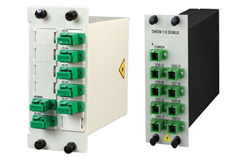
CWDM Mux and CWDM Demux are designed to multiplex multiple CWDM channels into one or two fibers. The core of CWDM Module application is the passive MUX DEMUX unit. The common configuration is 1×4, 1×8, 1×16 channels. Available in 19″ Rack Mount or LGX module package. Optional wide band port is available to multiplex with CWDM Channels wavelength.

(2)DWDM Mux/Demux Modules

DWDM Mux and DWDM DeMux are designed to multiplex multiple DWDM channels into one or two fibers. The common configuration is 4, 8, 16 and 40 channels. These modules passively multiplex the optical signal outputs from 4 or more electronic devices, send them over a single optical fiber and then de-multiplex the signals into separate, distinct signals for input into electronic devices at the other end of the fiber optic link

(3)Optical Splitter– a important component in EPON network

Optical splitter in optical communication era is a component of EPON network construction, is a connection of OLT and ONU passive device.

Its function is to distribute the downlink data, and focus on the uplink data. Optical splitter has an upstream optical interface, a plurality of downlink optical interface. Optical signals from the upstream optical interface over was assigned to the downstream optical interface out all transmissions, optical signals from the downlink optical interface over being allocated to uplink optical interface out transmission only. The light intensity signal downlink optical interface of each can be same, can also be different.

Multiplexer and demultiplexer

In telecommunications and computer networks, multiplexing (muxing) is a method by which multiple analog message signals or digital data streams are combined into one signal over a shared medium. The goal is to share an expensive resource. For instance, in telecommunications, several telephone calls may be carried using one wire.

The multiplexed signal is transmitted over a communication channel, which may be an actual transmission medium. The multiplexing divides the capacity from the high-level communication channel into several low-level logical channels, one for every message signal or data stream to be transferred. A reverse process, known as demultiplexing, can extract the original channels around the receiver side. A tool that performs the multiplexing is known as multiplexer (Mux), along with a device that performs the reverse process is called a demultiplexer (Demux).

In electronics, a multiplexer is really a device that selects one of several analog or digital input signals and forwards the selected input right into a single line. A multiplexer of 2n inputs has n select lines, which are used to select which input line to send towards the output. Multiplexers are mainly used to increase the quantity of data that can be sent within the network within a specific amount of time and bandwidth. A multiplexer can also be called a data selector. An electronic multiplexer makes it possible for several signals to share one device or resource. Conversely, a demultiplexer is a device going for a single input signal deciding on one of several data-output-lines, which is connected to the single input. A multiplexer is often combined with a complementary demultiplexer on the receiving end. A digital multiplexer can be viewed as like a multiple-input, single-output switch, and a demultiplexer like a single-input, multiple-output switch. The schematic symbol for a multiplexer is an isosceles trapezoid with the longer parallel side containing the input pins and also the short parallel side containing the output pin. The schematic around the right shows a 2-to-1 multiplexer on the left and an equivalent switch on the right. The sel wire connects the specified input towards the output.

In the fiber optic area, a WDM system also utilizes a multiplexer in the transmitter to join the signals together, and a demultiplexer in the receiver to separate them apart. WDM systems are divided into different wavelength patterns, CWDM and DWDM. There are different Mux Demux for every of these.

The DWDM equipment, a DWDM multiplexer, actually contains one wavelength converting transponder for every wavelength signal it’ll carry. The wavelength converting transponders get the input optical signal, convert that signal into the electrical domain, and retransmit the signal utilizing a 1550 nm band laser. Additionally, it contains an optical multiplexer, which takes the different 1550 nm band signals and places them onto a single fiber. And also the DWDM demultiplexer breaks the multi-wavelength signal back into individual signals and outputs them on separate fibers for client-layer systems to detect. DWDM Mux and DWDM Demux are designed to multiplex DWDM channels into one or two fibers. The most popular configuration is 4, 8, 16 and 32 channels. The DWDM modules passively multiplex the optical signal outputs from 4 or more electronic devices, send on them a single optical fiber and then de-multiplex the signals into separate, distinct signals for input into electronics in the opposite end from the fiber optic link.

At the same time frame, there are CWDM multiplexer demultiplexer (CWDM Mux and CWDM Demux). They’re made to multiplex multiple CWDM channels into a couple of fibers. The core of CWDM Module application may be the passive Mux/Demux unit. The most popular configuration is 4, 8, and 16 channels. Optional wide band port for existing 1310nm or 1550nm port is available to multiplex with these CWDM Channels. Along with the CWDM transceiver series or the wavelength converter series, the bandwidth of the fiber may be used in a economical way.

The Application of Fiber Optic Connector

fiber optic connectorFiber Optic Connector has been widely used in fiber optic transmission lines, fiber optic patch panels and fiber-optic test instruments and meters. The Fiber Connector is one of the most essential components for fiber optic communication. It mate or connect with optical devices, modules, and fibers. Fiber connector is also the key part used in fiber Patch cord and fiber Pigtail.
In fiber optics design, when the system is capable of normal operation, if you are trying to build the local network or LAN in your home then you most probably know you will need a fiber patch cable and may be a hub or we achieved a very good results. Choosing a good fiber optic modem depends on a few factors, including availability. We need to consider not only some unexpected problems appear in the system design, but also expect the system to achieve the effect of normal operation. During the process of system design, we have to consider the worst case appear and related plans, is looking forward to improved operating results. In system design, security, stability and system access request the end of the fiber is smooth, neat. The connection between the clients must be accurate, micron accuracy or millionths of a meter. The diameter of the commonly used multi-mode fiber is from 50 to 62.5 microns, while the diameter of the single-mode fiber is only 8-9 microns. This size of the diameter of a human hair can (17-180 microns) are compared in diameter, and we can make sure that every trace of error can bring catastrophic losses.

With the expansion of technology development and application of fiber optic patch cables are also achieving rapid development. The types of fiber optic connectors on the market are probably 12 or more, each of which was launched to the specific needs, of course, came to meet, there are some technical limitations. The trend in the market is developing at a moderate price, compact plug-mode and all can support the requirements of the new transmission distribution system. As users expect that the ongoing development of the telecommunications industry also supports the large-scale application of the optical fiber, in large part due to the rapid growth of demand in the way of communication and entertainment services on the fiber link.

The fiber optic connection is very stringent accuracy of the equipment, the species of fiber patch cords are many kinds. So the connector must be very clean. Fiber optic connectors and accessories are usually mounted on a series of house, a fingerprint or external dust seriously affect the performance of the connector, and even the loss of communication. Therefore, the connector can be stored in clean protective sleeve without connection. Then we should also put fiber optic connector.

Fiber optic connectors according to the different transmission media can be divided into common silicon-based optical fiber single-mode and multimode connectors, as well as other issues such as plastic and as the transmission medium of optical fiber connector; connector structure can be divided into: FC SC, ST, LC, D4, DIN, MU, the MT and so on in various forms. The optical interface is the physical interface used to connect fiber optic cable. FiberStore as the main professional fiber optic products manufacturer in china offer a various kinds of fiber optic connectors, FC Connectors, LC Connectors, SC Connectors, ST Connectors. You can buy fiber optic connection products on our store with your confidence. All of fiber optics supplies with high quality but low price.

What is a fiber optic coupler?

Fiber optic coupler is used to split the fiber optic light into several parts at a certain ratio. fiber optic coupler are important passive components used in FTTX networks. A fiber-optic splitter is a device that takes a single fiber optics signal and divides it into multiple signals. Fiber optic is a type of technology that uses an optical signal instead of an electrical one to send data from one place to another. The cable is made either of glass or plastic coated in plastic, instead of the copper wire that was commonly used in the past. But two kinds of fiber splitters are popular used, one is the traditional fused type fiber optic coupler (FBT coupler), which features competitive prices; the other is PLC fiber optic coupler, which is compact size and suit for density applications. Both of them have its advantages to suit for different requirement. The use of fiber optic technology has become increasingly popular for several reasons. Fiber optic cables are much less sensitive to electrical interference, marking them more reliable than older types of cabling. They are also able to carry very large amounts of data in comparison with that older systems can handle. This makes them very efficient, despite the facts that there are some drawbacks to the system. The cables  require a thicker covering to protect the optical cables and they also need to have repeaters installed to boost the signal strength in order for the system to work, two hindrances to the use of this technology.

Despite the limitations, fiber optics technology is in use for both home and commercial applications. The most common type of fiber optic coupler splits the output evenly, with half the signal going to one leg of the output and half going to the other. It’s possible to get splitters that use a different split ratio, putting a larger amount of the signal to one side of the splitter than the other. The Splitters are identified with a number that represents the signal division, such as 50/50 if the split is even, or 80/20 if 80% of the signal goes to one side and only 20% to the other.

Some types of the fiber optic coupler are actually able to work in either direction. This means that if the device is installed in one way, it acts as a splitter and divides the incoming signal into two parts, sending out two separate outputs. If it is installed in reverse, it acts as a coupler, taking two incoming signals and combing them into a single output. Not every fiber optic coupler can be used this way, but those that can are labeled as reversible or as coupler/splitters.

CWDM/DWDM Integration

CWDM/DWDM Integration

DWDM-CWDM integration – an easy-to-realize expansion of existing CWDM systems

CWDM/DWDM

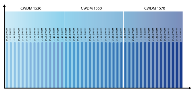
The difference between CWDM and DWDM lies in the channel spacing between neighbored wavelengths, for CWDM 20 nm and for DWDM 0.8/0.4 nm (using 100 GHz/50 GHz grid). Pan Dacom Direkt utilizes this advantage for an efficient CWDM/DWDM integration. Thereby up to sixteen DWDM channels are transmitted simultaneously in only one CWDM channel (1530 nm and 1550 nm). Thus an easy-to-realize channel extension can be achieved under continued use of existing CWDM components and thereby garantuees a protection of investment.

CWDM-DWDM integration – an easy-to-realize expansion of existing CWDM systems

What is DWDM

DWDM (Dense Wavelength Division Multiplexing)

DWDM definition:

Up to 40/80 wavelength over one pair of fiber

DWDM highlights

DWDM
DWDM
  • Up to 90 DWDM wavelength over one pair of fiber
  • DWDM channel spacing 0.8 nm (100 GHz grid) or 0.4 nm (50 GHz grid)
  • Distances over 1,000 km can be achieved with the use of optical amplifier
  • DWDM wavelength: 1528 nm (channel 61) to 1563 nm (channel 17)


DWDM principle

The functionality of DWDM resembles to the one of CWDM. Unlike to CWDM technology, the channel spacing for DWDM is 0.8/0.4 nm (100 GHz/50 GHz grid). This small channel spacing allows to transmit simultaneously much more information.Currently a restriction on wavelengths between 1530 nm and 1625 nm exists which corresponds to the C and L band. In this connection DWDM wavelengths from DWDM technology is more expensive compared to CWDM caused by the need of more sophisticated transceivers.

DWDM
DWDM


What is CWDM

CWDM (Coarse Wavelength Division Multiplexing)

CWDM definition: Up to 16 different wavelength over one pair of fiber.

CWDM highlights

Up to 16 wavelength over one pair of fiber

  • DWDM channel spacing 20 nm, 1720 nm to 1610 nm
  • Distances up to 120 km
  • Cost-effective WDM solution
  • Scalable by hybrid CWDM/DWDM – perfect solution for your investment


CWDM principle

CWDM
CWDM

CWDM is a wavelength multiplexing technology for city and access networks. Transmission is realized using 16 channels with wavelengths between 1270 nm and 1610 nm. Due to the channel spacing of 20 nm cost-effective lasers can be used. The channel width itself is 13 nm. The remaining 7 nm is designed to secure the space to the next channel.

What is WDM?

The IT refers to a medium where information is transmitted via a link. If two locations want to communicate with each other, one link is sufficient. To connect more locations more links are required What if only one link e.g. between two cities is available, but more applications shall be connected? Using the WDM technology, fiber optic links can be utilized for data transmission more efficiently.

WDM basics

The idea of xWDM technology

Each application is allocated to a dedicated color (wavelength) to communicate with a remote station. The advantage is that different colors can be simultaneously transmitted using one pair of fiber. For this purpose a multiplexer combines all different colors which will then be transmitted to the remote station over one pair of fiber. At the remote site the combined signal is separated again into different colors by a demultiplexer. Generally only one light beam with one wavelength is transferred over a pair of fiber. The wavelength multiplexing technology provides the ability to transmit more light beams, each having different wavelengths, using the same optical link. Due to the fact that wavelengths do not interfere, single light beams can be separated from each other using simple filters. A laser serves as the source of light and light-sensitive diode as receiver unit. Wavelength multiplexing is differentiated in CWDM (Coarse Wavelength Division Multiplexing) and DWDM (Dense Wavelength Division Multiplexing) technology. Advantage: With the use of WDM, it is possible today to transfer nearly 1 Tbps (C-band) via one pair of fiber.


FTTx: fiber to the home/Premises/Curb

FTTx: fiber to the home/Premises/Curb

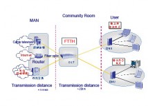
CATV companies are considering fiber to replace coax, since the cost is reasonable and performance unlimited. Municipalities or private individuals are looking at installing their own FTTH systems when phone or CATV companies won’t do it soon enough. Housing developers are learning about FTTH because their customers are demanding the highest bandwidth broadband connections.   DK Photonics

All these plans depend on finding or training adequate numbers of technicians. The FOA, working with operating companies, municipalities, installers and our approved schools has developed requirements for FTTx training and certification, with the goal of providing enough qualified FTTx installation technicians to make these plans possible.

FOA CFOS/H Certified FTTH Technician certification programs are now being introduced in many FOA-approved schools. Students seeking certification must complete the FOA CFOT program first to obtain their first level certification, then attend a short course on FTTx that will prepare them for the CFOS/H exam. Those interested in learning about FTTx but are not seeking certification will find the courses good information on the current technology.