What Is a Fiber-Optic Multiplexer?
A fiber-optic multiplexer is a device that processes two or more light signals through a single optical fiber, in order to increase the amount of information that can be carried through a network. Light wavelengths are narrow beams that ricochet through reflective optical tubing, sometimes over long distances, to provide instantaneous electronic signal processing at the speed of light. Multiplexers work by increasing a fiber’s transmission capacity using different techniques and light source technologies. When the signal arrives at its destination, a demultiplexer separates the data streams. Using a multiplexer also allows data to be sent farther, more securely, and with less electromagnetic and radio frequency interference.
Also known as a mux, the fiber-optic multiplexer saves time and cost by squeezing more information through the optical network pathway. It is possible to split signals by varying the schedule or period of each transmission. Time Division Multiplexing (TDM) combines multiple signals by rapidly alternating between them so that only one is transmitting at any given time. Statistical Time Division Multiplexing (STDM) assigns each signal a specific time slot in order to optimize bandwidth usage. Further techniques include divisions of wavelength and frequency.
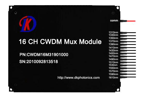
Wavelength Division Multiplexing (WDM) utilizes the total available pass band of an optical fiber. It assigns individual information streams different wavelengths, or portions of the electromagnetic spectrum. Similarly, Frequency Division Multiplexing (FDM) assigns each signal a different frequency. Carrier frequencies contain the signal while unused guard frequencies provide buffering to reduce interference. This helps minimize audible and visual noise and preserves the integrity of the original signal throughout the network.
Fiber-optic multiplexer technology serves single-mode and multimode optical fibers with multichannel rack mount or standalone units. This makes mixing channels with different configurations possible for a range of interface combinations. These devices provide stronger, more reliable transmissions in areas that have a lot of electromagnetic, radio frequency, or lightning interference.
As technology improves and information needs grow to fill the capacities of existing networks, equipment such as the fiber-optic multiplexer lessens the need to upgrade the fiber-optic infrastructure itself. Multiplexers permit new configurations of transmission protocols by increasing the amount of wavelengths or frequencies of light signals. By upgrading repeaters and terminal equipment, existing network transmission capacity can expand with demand.
Used by cellular carriers, Internet service providers, public utilities, and businesses, fiber-optic multiplexer technology extends the reach and power of telecommunications technologies. Network management systems allow for system service and maintenance, and provide for security, fault management, and system configuration. With advantages like lower costs and longer life expectancies, current fiber-optical networks are aided by improvements in multiplexing technology, and may provide light speed data transmission well into the future.
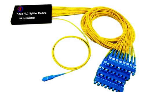
DK Photonics – www.dkphotonics.com specializes in designing and manufacturing of high quality optical passive components mainly for telecommunication, fiber sensor and fiber laser applications,such as PLC Splitter, WDM, FWDM, CWDM, DWDM, OADM,Optical Circulator, Isolator, PM Circulator, PM Isolator, Fused Coupler, Fused WDM, Collimator, Optical Switch and Polarization Maintaining Components, Pump Combiner, High power isolator, Patch Cord and all kinds of connectors.