A Short Yet Informative Post On Optical Fused Coupler

To make the work easy for the IT and telecommunication sectors, an optical fused coupler was introduced. And truly speaking, this technology proved its worth in both large and small scale requirements. 

An optical fused coupler works on a wavelength with the help of some scientific formulas. It transmits light waves in multiple paths with the help of two or more inputs. The primary role of the coupler is to complete the task simultaneously for more than one place using waves. 

The light waves are available in the form of either active or passive devices. Users often get confused between these two devices and end up evaluating things wrongly. Simply explained, the passive devices redistribute the signal without optical-to-electrical conversion and active devices split or combine the signals electrically. 

How does an optical fiber coupler work?

The working of an optical fused coupler is very simple. You just need to understand it carefully. Even amateur technicians can use the coupler and improve their telecommunication and IT jobs. 

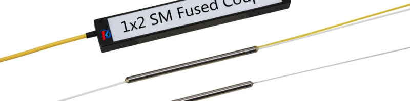
An optical fiber coupler contains N input ports and M output ports. The value of both input and output ports typically ranges from 1 to 64. It means you will find different categories of optical fused couplers with different numbers of ports. Generally, the couplers with four ports are available and used by the technicians. 

In the optical fused coupler, the light enters from one of the input ports and splits between two output ports. Similarly, remaining or other input ports function in the same way. In some cases, you will find that one input port remains unused. This is referred to as a T or Y type optical fused coupler. 

Types of optical fused couplers 

In the last para, we mentioned T and Y couplers. These are the different types of optical fused couplers. There are types as well. Here, we will explain T and Y couplers along with other types in brief. 

Y coupler– Also known as the optical tap coupler, the Y coupler resembles the letter Y. Just like the structure of the Y alphabet, the light waves split. In simple terms, the signal entering from the input port splits into two output ports. In this, you can control the power distribution ratio precisely. The sense is that it’s easy to meet your specific requirements.

T coupler– The structure seems very similar to the Y coupler, but the working is different from the T coupler. In this, the power distribution is uneven. The signal enters from the one input port and gets distributed into two output ports. The power distribution difference is that one output signal is greater than another output signal. 

X coupler– Though the name is a coupler, it carries out the function of both a splitter and a combiner. It means you will get two things in one package. In this, the coupler combines and divides the optical power from two input ports between the two output ports. Technically, the X coupler is also referred to as a 2×2 coupler. 

An optical fused coupler is an important technical development. It makes the work easier. The only thing is you should connect with the right manufacturer or supplier to get it for your job. 

The Need for Pump Combiners in Fiber Laser & Amplifier Applications

Pump Combiners, also called pump couplers, are optical passive components designed to send pump and signal light into a laser fiber or an optical amplifier. Basically, high-power fiber amplifiers and lasers are designed using rare-earth-doped fibers with double cladding.

Theoretically, one can inject both pump and signal light into the rare-earth-doped double-clad fibers. However, this technique is limited to research stages only. When it comes to industrial fiber laser applications, one needs an all-fiber setup where fiber pump laser diodes can be interfaced with the active fiber through some passive multimode (MM) fibers.

In such cases, one needs to use pump combiners for interfacing. The use of pump combiners helps achieve higher stability and better robustness in the devices. Some of the pump combiners are high-power pump combiners that are specifically made to safely handle power levels of several kW.

In the market, you will find two types of pump combiners. While the first type includes pure pump combiners, the latter includes pump & signal combiners that have an additional signal output.

Typically, pump combiners are denoted as:

Here, N represents the number of pump inputs.

For instance:

  • A 4 x 1 pump combiner means there are four pump inputs.
  • An (18+1) x 1 pump & signal combiner means there are 18 pump inputs and one additional signal input.

In general, there is no problem in not using all pump input ports except that there will be a loss in terms of pump brightness.

In addition, pump combiners are also available in the PM (polarization-maintaining) version.

Common Uses of Pump Combiners in the Industry

  • Pump combiners, including the ones with additional input, are extensively used for industrial high-power lasers. As mentioned above, they are needed to transmit the pump and signal light combined into the laser fiber.
  • Pump signal combiners are also widely used for erbium-doped fiber amplifiers (EDFA) that play a key role in optic fiber communications, such as cable-TV power amplifiers. While low-power EDFAs use dichroic fiber couplers that are based on single-mode (SM) fibers, high-power EDFAs based on double-clad fibers use multimode pumps & signal combiners.
  • Besides, pump combiners are also utilized in direct-diode applications where an output fiber is often a single-clad multimode fiber.
  • Other applications of pump combiners include fiber laser, fiber laser combination, kW class fiber lasers, and industrial research.

DK Photonics is a widely renowned pump combiner manufacturer based in China, offering standard and custom pump combiners, including N x 1 pump combiners, (N+1)X1 pump and signal combiners, and PM (N+1)X1 pump and signal combiners along with cladding power strippers (CPS). For any queries, please write to us at sales@dkphotonics.com.   

Define PM Optical Isolator & How It Differs from an Optical Isolator

Before understanding PM optical isolators, it’s important to know what optical isolators are. So, we will start by discussing the optical isolators and then help you find the answers you are looking for.

Definition of an Optical Isolator

An optical isolator is a passive component based on fiber-optics technology and allows the light signals to propagate in only one direction while blocking the reflections. An optical isolator consists of a Faraday rotator sandwiched between two polarizers.

Definition of a PM Optical Isolator

Here, PM stands for polarization-maintaining. A polarization-maintaining (PM) isolator is an optical isolator that guides optical light in only one direction while preserving its polarization state and eliminating the back reflections.

It blocks and isolates the system from the scattering of reflections in the reverse direction and helps improve the overall performance and efficiency of the optical and light-wave systems.

Why does polarization matter?

When dealing with applications and systems that utilize fiber optics technology, it’s critical to consider the polarization of the light. Even though the priority is given to the wavelength and intensity of the light in most optical systems, polarization is a crucial property of light that affects even those optical systems that don’t measure it explicitly.

Polarization of light has the capability to influence the focus of laser beams and the cut-off wavelength of filters. Plus, it also plays a substantial role in preventing unwanted back reflections.

Thus, for applications where you cannot allow the reflections of polarized light to impact the efficiency and performance of the systems and you need to maintain the polarization state of the light, what you need is a PM optical isolator.

What if PM optical isolators are not used in certain optical applications?

With the absence of PM optical isolators, the light source that emits the light wave or light signal gets exposed to back reflections and scattered signals that ultimately lead to intensity noise and optical damage. By using PM optical isolators, you can achieve greater isolation and higher return loss. Hence, they make the perfect choice for applications that are highly sensitive to optical feedback and reflections.

How are optical isolators different from PM optical isolators?

When it comes to differentiating optical isolators and PM optical isolators, the main difference is that the latter helps retain the polarization state of the incoming light while isolating the light source from any damage.

What You Should Know About Optical Isolators before Purchasing

When searching for optical isolators online, you will notice the term “TGG -based”. TGG (Terbium Gallium Garnet) is a crystal that is widely used as magneto-optic material in Faraday rotators that are the basic part of optical isolators and PM optical isolators.

The primary reason behind using TGG is that this material has excellent transparency properties, and it is highly resistant to laser damage.

When it comes to improving the performance of systems that use light waves, an optical isolator or a PM optical isolator is often a desirable component. However, sometimes, the expensive cost of optical isolators becomes a restriction. Thus, while buying optical isolators, people also look for affordable prices, in addition to their features and specifications.

DK Photonics manufactures PM optical isolators with a broad range of specifications and also caters to custom orders. For any queries related to optical isolators, please connect with us.

Essential Things to Know About Optical Circulators

In sophisticated optical communication systems, the optical circulator has become one of the most critical components. It’s used to split optical signals in an optical cable that is traveling in different directions.

Optical circulators have been widely used in a variety of disciplines, including telecommunications, medicine, and imaging. We’ll learn more about the optical circulator in this article.

What Is an Optical Circulator?

An optical circulator is a device that allows light to travel from one optical cable to the next. It’s a non-reciprocal device that routes light dependent on the propagation direction. Light can be moved forward using both an optical circulator and an optical isolator. In contrast to the optical circulator, the optical isolator often loses more light energy.

Optical circulators typically have three ports, two of which are utilized as input ports and one as an output port. A signal is sent from port 1 to port 2, followed by another signal from port 2 to port 3. Lastly, the third signal can be sent from port 3 to port 1. Because many applications only need two, they can be designed to prevent any light that enters the third port.

Optical Circulator Components Technologies

The following components make up an optical circulator:

Faraday Rotator

Faraday rotators use the Faraday effect, which is the rotation of the polarization plane of electromagnetic waves in a material subjected to a magnetic field parallel to the wave’s propagation direction.

Birefringent Crystal (Birefringent Crystal):

The polarization state of the light beam and the relative orientation of the crystal affect light propagation in the birefringent crystal. The beam’s polarization can be adjusted, or the beam can be split into two orthogonal polarization states.

Beam Displacer and Waveplate

Birefringent crystals come in two varieties: waveplate and beam displacer. A waveplate is formed by cutting a birefringent crystal to a particular orientation in which the crystal’s optic axis is parallel to the crystal border and in the incident plane. An entering beam is separated into two beams with orthogonal polarization states using a beam displacer.

Optical Circulator Classifications

According to the concept of polarization:

Polarization-dependent optical circulators and polarization-independent optical circulators are two types of optical circulators. The former is employed for light with a specific polarization state, whereas the latter is not limited to a light’s polarization state.

The vast majority of optical circulators used in fiber optic communications are polarization-independent.

In terms of functionality:

There are two types of optical circulators: full circulator and quasi-circulator. In a complete cycle, a full circulator makes use of all ports. Light travels from port 1 to port 2, then from port 2 to port 3, and finally from port 3 to port 1.

Light travels through all ports sequentially in a quasi-circulator, but the light from the last port is lost and cannot be sent back to the first port. A quasi-circulator is sufficient for most purposes.

Conclusion

You may now have a general idea of what an optical circulator is. Using an optical circulator to route light signals with minimal loss is a cost-effective and efficient approach.

Let’s Talk About Polarization Maintaining Fibers!!

When it comes to optical fibers always reveal some degrees of birefringence, regardless of having a circular symmetric design. This is because, in practice, there is usually some percentage of stress and other impacts that breaks down the symmetry. As an outcome, the polarization of light disseminating in the Fiber moderately changes in an unmanageable way which also bent the fiber and its temperature.

Principle Of polarization-maintaining Fibers

The mentioned issues can be repaired by utilizing a polarization-maintaining fiber component, which ain’t a fiber without birefringence; however, on the other hand, it is a specialty fiber with a powerful built-in birefringence. Considering that the polarization of light set in motion into the fiber is lined up to one of the axes of birefringent, no matter what comes in, this polarization phase will get properly preserved even if the fiber is in a bent state. Not to mention, the principle behind this can be comprehended as a mode coupling.

To your knowledge, the transmission sustains of the two polarization modes will always be varied because of the powerful birefringence. In this way, the relative phase of co-spreading modes will quickly bob away. Hence, any sort of hurdle along the fibers can efficiently couple all the two modes if only it has a dimensional Fourier component with wave digits that precisely go with the difference of the propagation constants of both the polarization modes. Just in case, if the variation is enormous enough, the usual disturbances, the poking in the fiber will do efficient mode coupling. To put it simply, the polarization beat length must be shorter than the typical length scale over which the parasitic birefringence varies.

Ways Of Realizing Polarization-maintaining Fibers Components

One of the most commonly utilized methods for introducing strong birefringence is to incorporate stress rods of altered glass composition (generally boron-doped glass, with a varied degree of thermal expansion) in the preform on different and opposite sides of the core. When a fiber is pinched from such kind of perform, it wouldn’t be wrong to say that the stress components lead to some mechanical stress with an accurate orientation. By making use of other methods, it is possible to make bow-tie fibers (where the stress elements have gotten a varied shape and go nearby to the fiber core) so that a stronger birefringence can be easily achieved. 

Single-mode and Few-mode Fibers: 

There is nothing wrong with stating that when it comes to polarization-maintaining fiber components, they are usually single-mode fibers. Having said that, however, only in seldom cases do polarization-maintaining components fibers come in few-mode fibers. The main reason behind this is- that it is arduous to manufacture strong and uniform birefringence in the fiberglass in comparison to the enormous core area where plenty of modes can be guided.

Applications: 

Polarization-maintaining fibers components are executed in devices where the polarization state isn’t permitted to drift, for example, as an outcome of temperature changes. Some examples are- fiber interferometers, fiber-optic gyroscopes, and certain fiber lasers.

What is a Fiber Collimator? Why is it needed?

Tell us the name of one common thing that you can find in various high-power components such as high-power optical isolators, fiber circulators, fiber optic attenuators, and CWDM/DWDM modules. All these components have one thing in common and that is called a high-power fiber collimator. In this blog, we will discuss high-power collimators in brief. So, if you want to know what these are and why they are needed, keep reading till the end.

What is a fiber collimator?

The meaning of the term “collimate” means to make light rays accurately parallel. Hence, a fiber collimator is a fiber optic component that is used to help change the diverging light from a point source into a parallel beam.

In other words, a fiber collimator is a simple module that consists of fiber and a lens and its basic function is to produce parallel beams.  

Fiber collimators are used to collimate the light at the fiber end and can also be used to couple light beams between two fibers. During the designing process of fiber collimators, utmost attention is given to the accurate adjustment of the fiber and lens so that parallel beams can be obtained.

Another thing you need to know is that the stronger the signal strength the higher the efficiency of the fiber collimator. And the fiber collimators that can handle a huge amount of power are categorized as high-power components.

An efficiently designed high-power collimator is characterized by low insertion loss, high-power handling capability, excellent temperature stability, and small beam convergence. Hence, it is considered an ultra-reliable device.

What is the need for fiber collimators?

In fiber optics applications, it is often necessary to transform the light output from an optical fiber into a collimated beam. For that, a simple collimation lens is considered sufficient. But the end of the fiber must be firmly fixed at a distance from the lens that is usually equal to the focal length. Thus, to make this more convenient in practice, a fiber collimator is used in fiber optics applications that require a collimated beam.

Fiber collimators can also be used for launching light from a collimated beam into a fiber or for fiber-to-fiber coupling where light from the first fiber is collimated and then focused into the second fiber by another collimator.

Another application of fiber collimators is the combination with a back-reflecting mirror and an additional element to achieve desired effects. For instance, you can insert a Faraday rotator to obtain a Fiberized Faraday mirror.

Other major applications of high-power fiber collimators are fiber lasers, fiber amplifiers, instrumentation, and test and measurement.

The Difference Between Active and Passive Optical Networks

In the optical network transmission process, we usually see the conversion of the electrical and optical signal at the input and output ports using a wide range of active and passive components. The light source is the foundation of optical fiber networks, and all the network transmission is always done in the form of light signals at input and output ports. It is why optical network engineers require active and passive components to design optical networks for accurate and efficient signal transmission and communication.

An optical network can either be an active optical network or a passive optical network, depending on the type and performance of the source signal. The active optical access network primarily employs Active Ethernet technology for point-to-point direct and single fiber bi-directional access, which improves bandwidth but with increased costs. As a result, passive optical access technology (PON) gradually took over the active optical networks to design cost-effective networks for light signal transmission.

What is Active Optical Network (AON)?

AON (Active Optical Network) refers to a network in which the signal is transmitted using a photoelectric conversion device, active optical components, and fiber optics. Optical lasers, optical amplifiers, optical transceivers, optical receivers, and other optical components are included in optical assemblies. The AON is a type of network that enables point-to-multipoint optical communication for a variety of industrial applications such as optical fiber transmission lines and optical remote terminals.

Features of AON Networks

  • Large transmission capacity
  • Long transmission distance without a repeater 
  • Mature technology 

What is Passive Optical Network (PON)?

Passive Optical Network (PON) refers to an optical distribution network (ODN) that doesn’t use any active devices or components for its operations. It includes optical passive components such as optical couplers, optical connectors, optical attenuators, optical isolators, optical circulators, optical switches, and so on in its building blocks. The Passive Optical Network (PON) is designed as an access network for optical fiber applications because it doesn’t use any active component that requires a power source to function. 

Features of PON Networks

  • Large transmission capacity
  • Long transmission distance
  • Low cost 
  • Excellent performance and scalability
  • High reliability
  • Great transparency of business

PON allows point-to-multipoint access network and fiber transmission at high security and low cost. Fast network construction is another advantage of a passive optical network over an active network. It is the most widely used optical network across industries as it is more convenient to scale and upgrade using optical passive components in comparison to AON technologies.