What Is An Optical Fused Coupler? How Does It Work?

A fiber optic coupler is an optical component that is widely used for distributing optical signals over the network. It is designed to distribute signals from one fiber to two or more fibers. In general, optical signals are attenuated more when used in an optical coupler. It is because of the fact that the input signal is not transmitted from one fiber to another directly but divided among different output ports.

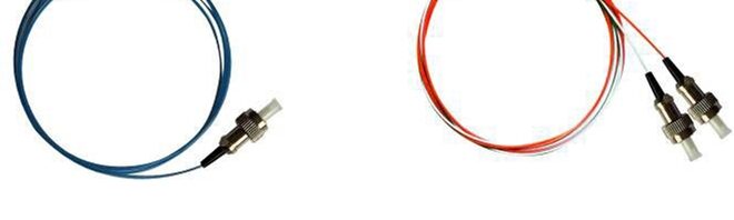
When it comes to defining an optical fused coupler specifically, it is important to understand that it is made of two parallel optical fibers that are twisted, stretched, and fused together to ensure that their cores stay in close proximity.

How does an optical fused coupler work?

The intensity profile of optical signals traveling in a single mode (SM) fiber is said to be Gaussian. Meaning, the intensity of light is greatest at the center and tapers off as the core or cladding interface ends. The rear ends of the Gaussian profile slightly goes further across the core and into the cladding. This extended tail at both ends is known as an evanescent wave.

In an optical fused coupler, the cores of two identical parallel fibers are so close that the evanescent wave can leak from one fiber core to the core of another fiber. This, in turn, allows an exchange of energy which is similar to the energy exchange that takes place in two coupled pendulums.

The amount of energy that gets exchanged varies depending on the closeness of two fused cores and the length over which energy exchange occurs. If the coupling length is long enough, complete energy may transfer from one core to another. If the length is even longer, the process will continue, transferring the energy back into the original core. Hence, with the selection of proper length over which energy exchange occurs, manufacturers can achieve any given power transfer ratio.

When the light is launched into an input port during the manufacturing process of a fused optical coupler, the output power that comes out of each output port is rigorously monitored. When the desired coupling ratio is achieved, the fully automated manufacturing process is also stopped. This results in a coupler made of one fiber with two cores that lie very close to each other. This process is called the Fused Biconical Taper (FBT) process.

Depending on the type of optical fused coupler, it is used in a variety of applications, such as CATV systems, optical fiber communication systems, testing instruments, FTTH and LAN optical networks, digital, hybrid, and AM-video systems, fiber sensors, mini EDFA, and small transmitter/receiver modules.

Are You Hesitant In Implementing WDM in Your Next Project? Know Why You Shouldn’t

Years ago, implementing WDM or wavelength division multiplexing in a telecommunication project was a huge task. And it’s because this technique required large, complex systems for proper functioning. Also, the systems were expensive. But today, things are different.

You will WDM with different configurations that are suitable for enterprises, data centers, government operators, and large-scale service providers. Most importantly, the available configurations are cost-effective.

There are many other things to know about WDM that can help your project in running smoothly. In this post, we will discuss some basics and important facts about WDM.

About Wave Division Multiplexing (WDM)

WDM functions by transporting different data streams through one strand of fiber. The transportation is done via differing light wavelengths. As compared to the single beam of light used to transport one data stream, on one wavelength, you will find lots of differences and improvements with WDM. There is no interference between the streams because multiple streams of data can be sent over the same fiber by assigning each data stream its wavelength.

With WDM, you can send data streams over independent channels while allowing for expansion and the addition of more channels.

The two categories of wave division multiplexing (WDM)

  • Coarse wave division multiplexing or CWDM
  • Dense wave division multiplexing or DWDM

The two categories of WDM are effective in increasing bandwidth capacity. Somewhat, these categories play a similar role in the implementation of WDM in a project. But, these categories have different channel configurations and have different advantages and disadvantages. The configurations depend on the environment CWDM and DWDM are used and the network challenges they face in the functioning.

Difference between CWDM and DWDM

The CWDM has a lower density with a shorter reach compared to DWDM. CWDM is used at a stretch of up to 80km or less where lower capacity isn’t an issue. On the other hand, DWDM provides higher density, higher bandwidth, and more accurate lasers. DWDM can be amplified to give a much longer reach but at a higher cost and technical complexity. DWDM possibly fits 40, 80, or up to 96 channels on the same fiber pair, which enables a huge amount of data to be pushed through the higher number of wavelengths available.

Working of wave division multiplexing (WDM) transceiver

WDM transceiver converts electrical signals from host equipment into optical signals to be transmitted via fiber. The conversion of the fiber is into a specific light wavelength with a unique color. You can add new channels without affecting existing traffic and transport a mix of data at different speeds over a single fiber of fiber pair simultaneously. The overall working of the WDM transceiver will depend on the selection of the CWDM or DWDM. They should match your multiplexer.

One major advantage of wave division multiplexing (WDM)

Scalability and flexibility- As an operator, you can divide and dedicate channels between many customers along with the organizations. It is easy to divide channels between departments and cope with the increased number of applicants with WDM. Most importantly, video and big data processing are clear.

After reading the post, we hope you won’t hesitate in implementing WDM in your next project.