CWDM Mux/Demux: Increase the Fiber Optic Network Capacity with These 4 Steps

Do you need to enhance the capacity of a fiber optic network without adding more fibers? If yes, CWDM Mux/Demux is the device you are looking for. To help you learn more about this, let’s discuss what it is and how to install it.

What does CWDM Mux/Demux mean?

CWDM is the acronym for Coarse Wavelength Division Multiplexing. This technology is specially developed to boost the fiber optic network capacity without requiring any additional components.

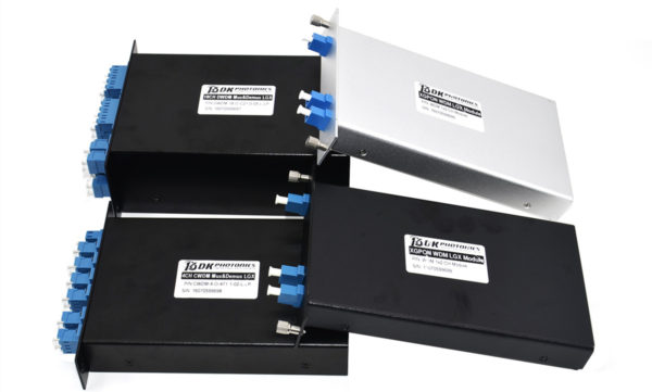
In a CWDM system, Mux/Demux is the most significant module as it helps in increasing the current fiber cable capacity by transmitting multiple wavelengths, up to 18 separate signals over a single fiber. This module is a passive device and easy to use. It can be availed in a variety of wavelength combinations, generally from 1270 nm to 1610 nm (20nm spacing).

Depending on different applications, it can be designed and manufactured into different channels. For instance, to multiplex 4 different wavelengths onto one fiber, a typical 4 channel Mux/Demux module is used. This will allow you to transmit four different data over the same fiber at the same time.

In case, you are using a CWDM multiplexer at the starting point of your network, you have to use a CWDM demultiplexer at the opposite end in order to separate the multiplexed wavelength or data so that they can be redirected to the correct receivers.

So, CWDM Mux/Demux is basically a module that can be used as a multiplexer or demultiplexer at either end of the fiber cable span. However, you still need to use it in pairs.

Things to Consider While Installing a CWDM Mux/Demux Module 

A typical CWDM Mux/Demux system consists of a local unit, CWDM Mux/Demux module, and a remote unit. The local and remote units refer to two different switches.

Before installing the module, a chassis needs to be installed first to hold the module. Then, CWDM SFP transceivers should be installed to connect the CWDM Mux/Demux module to a switch and after that transceivers should be connected to the module by using single-mode patch cables.

 To build a CWDM Mux/Demux System, we need a rack-mount chassis, CWDM SFP transceiver, and single-mode fiber cables.

Four Basic Installation Steps of CWDM Mux/Demux System

Step 1: Install the Rack-mount Chassis

Mount the chassis in a standard 19-inch cabinet or rack. During the mounting procedure, keep in mind that the chassis should be positioned in the same rack or adjacent rack to your system. This way, you can easily connect all the cables between the Mux/Demux modules and transceivers in the system with ease.

Step 2: Install the Mux/Demux Module

First, align the module with the chassis shelf and gently push the module in the shelf cavity. Then, secure the module with captive screws.

Step 3: Connect Mux/Demux to Switch

Insert the CWDM SFP transceiver into the switch. Once inserted, connect the transceiver to the Mux/Demux module with single-mode patch cable.

Note: The wavelength of the Mux/Demux module and transceivers should be the same because each transceiver will function at the designated port and data always transmit between devices that have the same wavelength. To make the connection, you can use color code of the transceiver.

Step 4: Connect the Mux/Demux Pairs

After using CWDM multiplexer at one end of the network, install CWDM demultiplexer at another end. Your last step would be to connect this pair. If you are using duplex Mux/Demux, you should make the connection by using a pair of single-mode patch fiber. However, for simplex Mux/Demux, only one single-mode patch fiber is sufficient.

Once you go through all these steps, your CWDM Mux/Demux system will be successfully installed.

Need to Use High Power Isolators and Their Different Types

High power isolator plays an important role in industrial control systems. Also known as a signal isolator, it basically isolates, input, output, and the working power from each other. Therefore, it is mainly installed in those equipment and systems that require electrical isolation. In other words, an isolator is a mechanical switching device that allows the isolation of the input and output of the device in the open position. To meet the varied requirements of different applications, it is available in different specifications such as 1064nm High Power Isolator, 1080nm High Power Isolator, 1030nm high power isolator, 980nm high power isolator, and so on.

In this post, you will learn about the need of isolators and their types.

Reason to Use Isolators

Isolators are mechanical switches that are used to separate the part of electrical power. They can open a circuit under no load. The main purpose of using isolators in systems is to isolate one portion of the circuit from the other which is not intended to be opened while current is flowing. They are generally used on both ends of the break so that repair or replacement can be done without any danger.

Reasons for Interference in the System

There are several reasons which make the systems unstable such as:

  • Weak signal transmission in automation instrumentation, control systems, and actuators
  • Use of Small (millivolt, microampere) to large signals (thousands of volts, hundreds of amperes)
  • Signal systems with low frequency to high-frequency pulse

In addition to this, anti-electromagnetic interference is also an important factor. The presence of a potential difference between instruments and equipment between signal interference points leads to the formation of ground loops caused during signal transmission in the distortion process.

So, the problem of ground loop must be solved in the process of system signal processing to ensure the stable and reliable operation of the system.

Possible Solutions to Ground Loop Problem

According to theory and practical analysis, there are three solutions to the ground loop problem including all site equipment grounding, creation of the same electrical potential of two junctions and signal isolation method.

Among all of them, signal isolation is the most suitable and practical solution as it can break the loop without interfering with the normal transmission of the process signal. Thus, it can be used to completely solve the ground loop problem.

Types of Isolators

There are different types of isolators based on the requirement of the system.

  • Single-break Isolator – in which arm contact is separated into two elements
  • Double-break Isolator – consists of three loads of post insulators
  • Pantograph Isolator – permits current switchgear installation and requires the least space

However, according to the power system location, they can be categorized into three types, for instance:

  • Bus Side isolator – which is connected by the major bus
  • Line Side Isolator – which stays connected by a feeder in line side
  • Transfer Bus Side Isolator – which stays connected by the major bus of a transformer

If you are in need of any type of isolator including 1064nm high power isolator, 1080nm high power isolator, or isolators in other customized specifications, ensure that you contact a high power isolator manufacturer online that has a strong presence and reputation in the market.

Polarization Maintaining Tap Coupler: Features & Major Applications

The polarization maintaining (PM) tap coupler basically provides optical signal splitting with tap ratio while also preserving the exact state of polarization. By combining the PM collimators and thin-film filter technology, the polarization maintaining coupler features high return loss, low insertion loss, environmental stability, and high extinction ratio.

The PM tap coupler splits the light coming from the input PM fiber into two outputs PM fibers. The polarization state further can be aligned with the fast axis or the slow axis of the polarization maintaining fibers. The stainless steel and rugged tap coupler are mainly designed for stability as well as high optical performance. The device with split ratios from 1 to 50% is now available so you can utilize it accordingly to your needs.

Some major applications of polarization maintaining tap coupler:

There are various applications of PM tap coupler, among which the major ones include:

  • Monitoring signal in polarization maintaining fiber systems
  • Fiber sensors
  • Helps in power-sharing of polarization-sensitive devices and systems
  • Polarization maintaining interferometers
  • Fiber optic devices and instruments
  • Coherent detection

Polarization maintaining tap couplers are made of separate crystals of lights and the output port of lights emitted is different from the polarization filter coupler. The coupling ratio is more accurate, while it can also handle high power as compared to the PM filter couplers.

On the other hand, the PM couplers can also be used to split high power linearly polarized light into different paths and that too without disturbing the state of polarization (SOP). Furthermore, it can even be used as a power tap for monitoring the signal power in the PM fiber system that functions without perturbing the linear state of polarization (SOP) of light in the polarization maintaining fiber.

Features of polarization maintaining tap coupler:

Some of the major features of PM tap couplers include:

  • Low insertion loss
  • Compact inline package device
  • High stability power
  • Can handle high energy and power
  • The optimum optical performance in a different environment
  • Excellent credibility
  • High extinction ratio
  • Accurate tap ratio
  • Accurate coupling ratio

So, these are a few primary features and applications of polarization maintaining tap couplers that you must be aware of. Besides, if you have the requirement of this device or any other type of PM coupler with tailored specifications then you may simply talk to PM coupler manufacturers and get the best assistance for the same. Just be sure to consult the right manufacturer so you can be confident that you are investing your money and time on the right device and at the right place.

Use and Working of High Power Faraday Rotators and Isolators

Faraday rotators and isolators are commonly used in telecommunication, electronics, and other industries. However, you may have noticed that there are many companies which offer high power Faraday rotators and isolators. Just due to the addition of two words “high” and “power”, most people wonder whether they are different from the typical ones, what these components are, when they are used and how they work. If you are one of them who are curious to know all such things, you have landed at the right place as here we have discussed answers to all these questions.

By definition, high power Faraday rotators and isolators are similar to the typical ones. While rotators are magneto-optic devices which are used to rotate the polarization state with the use of Faraday Effect, isolators are the components which transmit light in a specific direction and block the light traveling in the opposite direction.

When High Power Faraday Rotators and Isolators are Used

At high power, there is a high possibility of damage or disruption in the operation of the laser system through optical feedback. Thus, a high power faraday isolator is inserted in the system to reduce this feedback. Since they are based on Faraday Effect and are passive, unidirectional and nonreciprocal devices that employ the phenomenon of magneto-optic rotation, they can isolate the source and protect the laser oscillator from reflections in an optical system. In brief, they act as optical diodes that allow the propagation of light in only one direction.

Construction and Working of High Power Faraday Rotators and Isolators

Faraday isolators consist of a Faraday rotator, two polarizers, and a body to encapsulate the parts. On the other hand, the Faraday rotator is made of magneto-optically active optical material which is placed inside a permanent magnet.

Let’s consider an example of a Faraday optical isolator in which the magneto-optical rod is cut from glass that is polished to the flatness of λ/10 and has a parallelism better than 10 arc seconds. It is coated for anti-reflection with a residual reflection of <0.2% each side in the range of about 765-835 nm.

The polarizers are made from an air-spaced material such as Glan prism made of calcite. The entrance and exit faces of polarizers are coated with anti-reflection material with a residual reflection range of <0.3%. Polarizer transmittance is more than 98%. So, in this case, this will provide a total transmittance of better than 85% for the isolator.

The unpolarized or polarized laser light is entered through input polarizer and linearly polarized to 0 degree. Next, the linearly polarized light will enter through Faraday rotator rod and the plane of polarization will rotate as the light propagates along the rod axis. The Faraday rotator is tuned for rotating the plane of polarization to 45 degrees. Then, the light passes through the output polarizer whose transmission axis is also at 45 degrees.

Any light that reflected back re-enters the isolator through output polarizer and becomes polarized at 45 degrees. This light then passes through Faraday rotator which produces another 45 degrees of rotation to make the light polarized at 90 degrees or horizontally before being stopped or blocked by the polarizer, still at 0 degrees.

Thus, the laser light is isolated from its reflections. This is how high power Faraday rotator and isolator work together.