Fiber Optical Coupler: Design, Working, and Its Types

An optical coupler is one of the most commonly used devices in the telecommunication and electronic industry. Since its introduction, it has become an extremely important component in various phonic devices and systems. It is widely used for coupling or splitting light waves through waveguides or fibers and can be availed in the form of either active or passive devices. The main difference between active and passive couplers is that the passive coupler redistributes the optical signal without converting optical signals into electrical form. On the other hand, active couplers split or combine the signal electrically and make use of fiber optic detectors and sources for input and output.

A basic fiber optical coupler usually contains N input ports and M output ports and their value typically ranges from 1 to 64. However, in general, they are available with four ports and their functioning relies on the coupling distributed between two separate waveguides placed in close proximity. It results in a gradual power transfer between the modes that are supported by two waveguides.

The working principle is quite simple of these couplers. When the light enters from one of the input ports, it will be split between two output ports. The remaining second input port also functions in the same way. Sometimes, one of the input ports remains unused. In this case, the fiber optical coupler acts as a Y or T coupler (where Y or T depicts the form of transmission route).

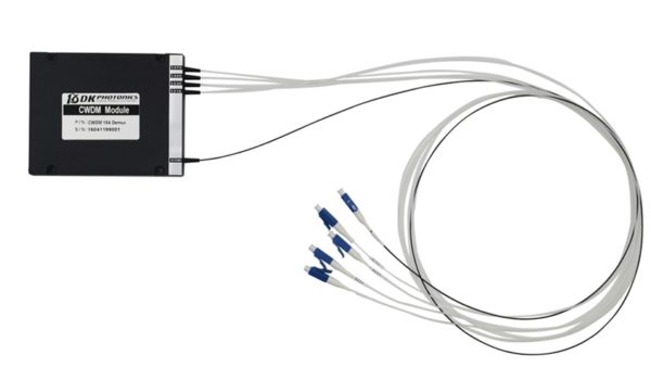
Since fiber optical coupler can couple or split the light, it can be also be called fiber optic splitter. In fact, splitter name is used due to the function of device and coupler name is used for it its working principle. Nowadays, the most common types of fiber optical coupler are optical fused coupler and planar light wave circuit (PLC) splitter.

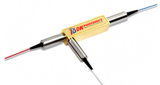
Optical Fused Coupler

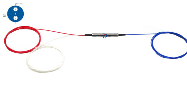
Also called fused fiber optical coupler, it is formed on the basis of fused biconical taper (FBT) technology. Therefore, it is also known as FBT coupler. Generally, it is available to work on three different operating bandwidths such as 850 nm, 1310nm and 1550nm. However, it can also be ordered to manufacture for operating on other bandwidth values. Its remarkable features are low excess loss, low PDL, excellent reliability and high stability.

Planar Lightwave Circuit (PLC) Splitter

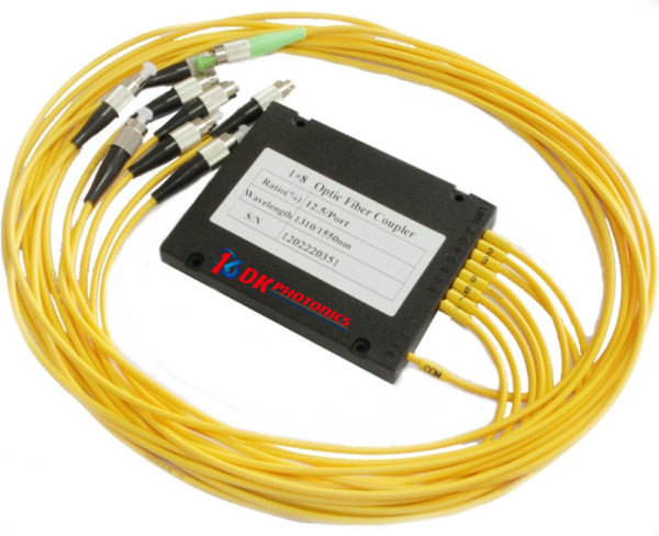
PLC splitter is especially designed to manage the optical power signals via splitting and routing. It offers reliable light distribution and is manufactured based on planar lightwave circuit technology. When compared with optical fused coupler which is available at lower cost, this splitter has a wider operating wavelength range varying from 1260nm to 1620nm and wider temperature range from -40ºC to +85ºC. It is also widely known for better uniformity, higher reliability, and smaller size.

These days, a typical fiber optical coupler is widely used to support FTTX (FTTP, FTTH, FTTC, and FTTN), passive optical networks (PON), local area networks (LAN), CATV systems, amplifying, monitoring systems and test equipment. Nonetheless, no matter for which application you need to use an optical fused coupler or PLC splitter, it is always beneficial to look for high quality devices, as their performance greatly varies with the material and their construction. So, when it comes to buying fiber optical coupler, you should always choose a copper-bottomed company.

DWDM Mux/Demux: A Quick Look at Everything, Features to Applications

Wavelength division multiplexing (WDM) is a kind of technology, commonly used in optical communications. It works by combing multiple wavelengths to transmit signals on a single fiber. CWDM and DWDM mux/demux are the essential part of this process.

WDM mux and demux have several different ports, each with a different function to perform.  We will discuss each of them, looking at their applications.

A Sneak Peak into Ports on WDM MUX/DEMUX

There are five major ports used on the MUX/DIMUX. Have a detailed look at each of them below.

Line Port

Sometimes, also called common port, this is the one of the most important ports that must be on CWDM and DWDM Mux/Demux. It helps to connect the outside fibers often marked as Tx and Rx to the Mux/Demux unit. All the WDM channels are multiplexed and demultiplexed over this port.

Channel Port

Channel port is another must-have port, which transmits and receives signals on specific WDM wavelengths. Because of this port, CWDM Mux/Demux can support up to 18 channels from 1270nm to 1610nm with a channel space of 20nm. While DWDM Mux/Demux uses wavelengths anything between 1470nm and 1625nm, services or circuits can be added in any order to the Mux/Demux unit.

Monitor Port

This port on CWDM and DWDM Mux/Demux helps test the dB level of the signal. And the best thing about the port is that service is not interrupted during the signal test, which provides users with the ability to monitor and troubleshoot networks. If your Mux/Demux is a sing-fiber unit, use the monitor port which is simplex one.

Expansion Port

This port aims to expand more wavelengths or channels to the network. Connecting the expansion port with the line port of another Mux/Demux supporting different wavelengths, you can increase the network capacity. However, not every WDM Mux/Demux has an expansion port.

1310nm and 1550nm Port

These are wavelengths ports that enable optical transceivers, especially the CWDM and DWDM SFP/SFP+ transceiver to support long runs transmission. Using these ports, you can add 1310nm or 1550nm wavelengths into existing WDM networks by connecting with the same wavelength optical transceivers.

Application Cases of Different Ports on WDM MUX/DEMUX

While WDM Mux/Demux have many different ports, you do not need to use all of them at the same time. Here are some examples of their applications.

  • Use 8 Channels CWDM Mux/Demux with Monitor Port where two switches/routers are connected over CWDM wavelength 1511nm.
  • Achieve 500Gbps at Existing Fiber Network with 1310nm Port
  • Stack Two CWDM MUX/DEMUX Using Expansion Port

As we know different ports on the CWDM and DWDM Mux/Demux have different functions, you should buy DWDM Mux/Demux with ports that precisely meet your requirements. If you are looking for DWDM Mux/Demux for the best price, you can trust, DK Photonics – a leading supplier optical passive competent in China.

Single Fiber CWDM Mux/Demux and Selection of a Transceiver for This Device

When it comes to transmission and reception of the same wavelength in CWDM network, the one thing that is widely used in this industry is – bidirectional CWDM Mux/Demux. This compact device finds its extensive usage in various applications, especially in telecommunications. Often used in dual way transmission applications, its working is based on a simple principle. When there is a need to connect two dual fiber CWDM Mux/Demux, a dual fiber cable supporting the same wavelength is installed on each end of the fiber network. Even though the wavelengths of the two fibers are the same, they run in different directions of the duplex transmission.

CWDM MuxDemux

However, there is only one fiber for expanding network capacity in some cases. In such cases, we use single fiber CWDM Mux/Demux which is quite different from the dual fiber type. Here, we will discuss what this single fiber CWDM Mux/Demux is all about.

Single Fiber CWDM Mux/Demux

The biggest difference between the appearance of dual fiber and single fiber CWDM Mux/Demux device is that the single fiber type has a simplex line port. However, some of them are also made with a duplex port in which only one port of the duplex is available for use and the other one is marked with N/A.

The main reason behind why this Mux/Demux is capable of achieving dual way transmission is that it utilizes CWDM wavelengths in a different manner as compared with the dual fiber type. While in bidirectional CWDM network each of the wavelengths runs in two opposite directions, in unidirectional CWDM network, they run in just one direction.

So, if you want to create a dual way transmission link between two different sites, you can use either one wavelength over duplex fiber with dual fiber CWDM Mux/Demux or two wavelengths over simplex fiber with single fiber CWDM Mux/Demux.

But, how do you choose a fiber optic transceiver for the single fiber type Mux/Demux? Let’s check out.

How to choose a Transceiver for Single Fiber CWDM Mux/Demux?

While selecting a fiber optic transceiver for the single fiber type, many people get confused because there are two different wavelengths on a duplex channel port. You need to make the selection based on only one thing and that is the wavelength value for Tx.

For example: If Tx value is 1290nm, you should buy a 1290nm CWDM transceiver, if Tx value is 1270nm, you should buy a 1270nm CWDM transceiver and so on. So, you can easily select a transceiver for single fiber type device without any confusion.

If you are also looking for CWDM Mux/Demux for your application, just contact a reputed manufacturer online and get the quotation today.

What to Know Before Buying Optical Circulator

Optical circulator is something used to monitor the optical power traveling in optical fiber. Either it can be used to polarize lights flowing different directions into a single direction or light in the single director into several directions.

There are varieties of Polarization Insensitive Optical Circulators meant to serve different purposes. Choose an optical circulator based on what you want to achieve.

What is Optical Circulator?

Optical circulator is a non reciprocal device used to allow the routing of light from one fiber to another, and this happens based on the direction of the propagation.

A special fiber optical component, optical circulator is used to separate optical signals in an optical fiber. It comes with three ports, and they are designed in a way that when light enters any port, it will exist from the next. This feature of high isolation of the input along others such as optical powers, low insertion loss, makes optical circulator a device widely used in a wide range of advanced communication systems and fiber optical sensing devices.

There are many manufacturers in China offering different types of optical circulators such as Polarization Insensitive Optical Circulator. If you are looking high quality circulators designed to your specific needs, and the best most competitive price, DK Photonics which offers a wide range of optical passive devices including the most widely used Polarization Insensitive Optical Circulator can be the right choice for you.

Polarization Insensitive Optical Circulators offered by DK Photonics comprised of several world-class features such as:

  • Low Insertion Loss
  • High Isolation
  • Low PD
  • High Stability and Reliability
  • Cost Effective

These are a few of the features that make the circulator highly suitable for the use in a wide range of applications. Polarization Insensitive Optical Circulators are widely used in:

  • DWDM Systems
  • Optical Fiber Amplifier
  • Pump Laser Source
  • Fiber Optic Sensor
  • Test and Measurement
  • Instrumentation

How to does the optical circulator work?

The Polarization Insensitive Optical Circulator which is used in fiber optical system directs the light/optical signals from one port to another. This helps prevent the signals transmitting in undesired direction. In a circulator which has three ports, signal is pushed from one port to the second port, and the another signal is directed from the port second to port 3 and at last, a third signal is transmitted from the last port to again to the port one. This is how the circulator helps you control the light and direct the signals into desired direction.

Role of an In-Line Polarizer in Communication System

In the telecommunication industry, the use of optical devices has increased dramatically as they offer high performance, optimum efficiency and excellent reliability. But the truth is that deploying light waves is not easy because they are highly susceptible to noise and interference. Fortunately, these issues can be resolved by the use of fiber optic polarizers. They greatly enhance the signal performance in fiber optic systems by suppressing unwanted interference patterns.

Fiber optic polarizers are placed inline so that the extinction characteristics of the fiber optic cable get improved. Due to their inline placement, these are also called in-line polarizers. The good thing about these polarizers is that they allow the transmission of only one polarization and block the remaining light which has unpolarized states.

So, to maintain the polarization and decrease the degradation in polarization, optical polarizers are necessary. Otherwise, there will be noise interference and the performance of the entire fiber optic system will decrease substantially. An ideal fiber optic inline polarizer is the one which transmits linearly polarized light that has a high extinction ratio and low insertion loss.

Here, linear polarization means the electric or magnetic field is confined to the plane in the direction of wave propagation. Extinction ratio refers to the ratio of the power of a plane-polarized beam transmitted by the polarizer to the transmitted power when polarizer’s axis is perpendicular to the plane of beam and insertion loss is defined as the attenuation caused by the insertion of an optical component.

Characteristics

The light waves transmitted by fiber optic systems are usually characterized by the length of wave i.e. wavelength. The carrier signal is further determined by the signal’s optical power which is measured in dBm or mW.

Wavelength: Human eye can detect wavelengths from 400 to 700 nm which is referred to as visible region. However, fiber optic systems transmit the longer wavelength from red (650 nm) to infrared region. It is caused by the characteristics of the transport medium i.e. the optical fiber. Shorter wavelengths are attenuated due to the scattering effect of light source and they are further attenuated by the absorption bands at specific frequencies.

The main three wavelengths which are used for fiber optic systems are 850, 1300, and 1550nm. 850nm wavelengths are primarily used in plastic optical fiber and multimode fiber. Multimode fiber can also be used to transmit 1300 nm carrier signals, however, single mode fiber can transmit even longer wavelengths such as 1310nm, 1490nm, and 1625nm.

Optical Power: The power of an optical signal is a measure of wavelength and photon density. Fiber optic communication systems use very low power signals. It can be measured in dBm and mW. dBm and mW have logarithmic relationship. The power level of 0 dBm is equivalent to 1 milliwatt.

If you are also searching for fiber optic in-line polarizers, you can easily place an order with a reputed polarizer manufacturer online.

What is CWDM Mux/Demux and what it is used for?

Wavelength Division Multiplexing (WDM) is a technology which allows you to expand the capabilities of your existing fiber optic network without the addition of extra optical fiber. Through this technology, a Mux can multiplex various optical signals of different wavelengths on a single optical fiber without the need for additional optical fiber. This helps a lot in relieving the fiber exhaustion and extending the link capacity.

In general, there are two types of Mux/Demux – CWDM and DWDM. In this blog, we will discuss the CWDM type in detail.

CWDM

CWDM stands for Coarse Wavelength Division Multiplexing. A CWDM Mux/Demux is used to increase the capacity of the fiber in 4, 8, 16, or 18 channels. By incrementing the channel spacing between different wavelengths, this device allows an easier, simple and affordable method to carry up to 18 channels on a single fiber. It is mainly used for providing the flexibility to increase the capacity of existing fiber infrastructure.

Application of CWDM Mux/Demux

This device is widely used in a number of applications such as:

  • WDM network
  • Line monitoring
  • Cellular application
  • Access network
  • Fiber amplifier

Each of the CWDM channels uses 20nm of space and all of them consume most of the operating range of single mode. Every channel carries data independently and there is no effect of one channel on the other channel. This allows network designers to transfer different data rates and protocols to meet the different requirements of different customers without any interference. The usual operating wavelength range for 16 channels varies from 1270 to 1610 nm and the most commonly used CWDM Mux/Demux are the ones which come with 16 or 18 channels.

So, which one you should choose for your application? Let’s find out.

16 Channel vs. 18 Channel CWDM Mux/Demux 

The capacity of a CWDM network largely depends on Mux/Demux. If there are more channels of Mux/Demux, the capacity of CWDM network will also be higher. The channel number of most of the Mux/Demux ranges from 2 to 18. Among these, 16 and 18 channel CWDM Mux/Demux devices are more commonly used in the telecommunication industry. Except for the fact that the latter one provides two more channels than the former, there is no difference between them. Since in CWDM Mux/Demux with 18 channels, the capacity is increased, there will be more insertion loss.

So, there is no such thing about superiority between these two. Which one you should choose depends on your specific requirement and application scenario. If your application involves broader network capacity and scalability, an 18 channel CWDM Mux/Demux is recommended to use, otherwise you can go for 16 channel CWDM Mux/Demux.

All you need to know about polarization maintaining optical circulators: a few major pointers!!

Since several years, Polarization Maintaining Optical Circulator has become an important element in the optical communication system. But these days, its applications have expanded not only in the telecommunication field but also in imaging and medical field.

In this blog, we’ll discuss on Polarization Maintaining Optical Circulator in more detail, but before that let’s know a few basic regarding it.

To begin with, let’s discuss what exactly is an optical circulator?

An optical circulator is mainly a multiple port non-reciprocal passive component. Its function is just similar to that of a microwave circulator, i.e. to transmit the light wave from one port to other with maximum intensity. But, at the same time, it also blocks any light transmission from one port to its previous port. Besides, the entire optical circulator process is based on the non-reciprocal polarization of the Faraday Effect.

What are the features of Polarization Maintaining Optical Circulator?

There are various features of polarization maintaining optical circulator. Mentioned below are a few major ones:

–    It has a high stability

–    It has a low insertion loss

–    It has high reliability

–    It has high optical return loss and so on.

How can optical circulators be categorized?

Optical circulators typically can be categorized into two main streams namely:

–    Polarization-dependent optical circulator, and

–    Polarization independent optical circulator

Polarization-dependent optical circulator is functional only for a light wave with a specific polarization state. This type of optical circulator is used only in some of the applications that mainly include free space communication between crystal sensing and satellites. Whereas the polarization independent optical circulator is independent of the polarization state of light. In the ordinary circulators, the polarization is certainly not maintained, however, there are polarization maintaining optical circulators available, so they can be used on behalf of it.

Besides, they can also be utilized in a wide variety of applications, but depending on its functionality, optical circulators may be divided into two groups:

–    Quasi circulator: In this circulator, the light passes through all the multiple ports, but the light from the last port is lost.

–    Full circulator: In this circulator, the light passes through all the multiple ports in a full circle.

When it comes to circulator’s design, there are many variations, but, all the non-reciprocal rotation designs certainly share the same structure with at least three functional elements namely- non-reciprocal polarization rotation elements, polarization recombining, and splitting elements, as well as polarization dependent beam steering elements.

Finally, we can say that with the large development of advanced optical networks and elements, the application of optical circulators are rapidly growing and new and advanced applications and functionalities are emerging quickly.