What is CWDM and its features?

Multiplexing is the method of maximizing the communication capabilities with the use of fiber optic cables. This methodology maximizes the communication capabilities and CWDM (Coarse Wavelength Division Multiplexing) combines multiple signals along the fiber optic cable on laser beams. Various wavelengths and channels are used for transmission and the functionalities are much higher than conventional standard Wavelength Division Multiplexing (WDM).

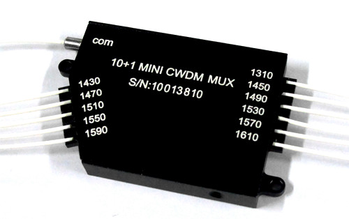
What are the specifications of a compact CWDM Mux and Demux?

Low-cost, un-cooled lasers are used for CWDM and the system has channels at wavelength spaced 20 nanometers (nm) apart. The emission is occurring at 8 different channels namely – 1610 nm, 1590 nm, 1570 nm, 1550 nm, 1530 nm, 1490 nm, and 1470 nm. Also, up to 18 different channels are allowed with the wavelength ranging down to 1270 nm.

The energy emitted out of the lasers in a CWDM is spread out over a larger range of wave=lengths which is the energy from the lasers in a DWDM system. The tolerance is much higher up to ± 3 nm. A CWDM system is less expensive and consumes less power than a DWDM system.

Features of CWDM MUX or DEMUX

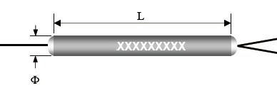
  • It is compact and mini in size
  • The device has low insertion loss
  • It has wide pass band
  • High channel isolation is possible with CWDM
  • The state of CWDM MUX or DEMUX is highly stable and reliable
  • It ensures Epoxy Free on optical path

Application that uses compact CWDM MUX or DEMUX

  1. Line Monitoring
  2. WDM Network
  3. Telecommunication
  4. Cellular Application
  5. Fiber Optical Amplifier
  6. Access Network

The optical signal is multiplexed from 4 or more devices into a single optical fiber. De-multiplexing is splitting a signal into separate signals for input into the electronic devices. It provides the ability to add or drop a single wavelength from a multiplexed signal which is providing access to common fiber segment between remote sites. The channel segmentation is very high in CWDM and the expanded seclusion prompts better outcomes. The CWDM channel arrangements have their utilization and applications additionally in the Cellular area. It devours Channel-8 CWDM at an incredible rate. The items should be utilized for straightforward transmission of signs and also use of filaments.

PM Fiber Coupler Enables Better Communication with Resistance to Environmental Effects

What is an optic fiber coupler? It is an optical device connecting the fiber ends for transmission light waves. These waves are then diverted into different paths. It is capable of combining two or more inputs into a single output and also divides a single input into two or more outputs. The optical coupler is constructed by fusing and tapering the fibers. What does it do otherwise? It splits optical signals between two fibers. The fused coupler is developed using fusing technique and polarization maintaining fiber coupler.

Polarization Maintaining Fiber Coupler

They are manufactured in such a way that a high polarization extinction ratio (PER) is launched along the slow axis of the fiber. Certain applications for PM couplers include optical sensors, optical amplifiers, and fiber gyroscopes. They provide an improved PER (≥20 dB including connectors) and a wide -40 °C to 85 °C operating range. The couplers undergo extensive testing and verification of the PER and they are available with 2.0 mm narrow key FC/PC and FC/PC connectors.

Let us now look at the characteristics and applications for PM Fiber Fused Coupler

  • It features Low Insertion Loss
  • Also, it has higher extinction ratio
  • Available in compact In-Line Packaging
  • 100% stability and reliability is ensured
  • Uniformity is maintained with high directivity
  • The wavelengths vary from 780 nm-2005 nm
  • Most preferred for fiber optic instruments and fiber sensors
  • Researchers use them in the best possible way and coherent detection is enabled

What is the use of Polarization Maintaining Fiber Coupler?

They are more useful in optical communication and transmission. The availability is in the configuration of 1×2, 2×2, 1×3 (monolithic) and 1×4 (compact cascaded). They are also monolithic in character with operational wavelength up to ±20 nm for 1550 nm region devices. Fused PM splitters are also available on smaller core fibers for various wavelengths like 1064 nm, 980 nm, and other wavelengths.

Additional features of PM Fiber Coupler………..

  1. Evanescent Wave Coupling
  2. Compact Silicone Rubber Package
  3. Advanced wavelength
  4. Multiple coupling ratios

The IL will be 0.3dB higher and RL will be 5 dB for devices with connectors. The manufacturers of fiber couplers offer custom coupler configurations with other wavelengths, fiber types, coupling ratios, alignment axes, or port configurations. The values are specified with a slow axis launch at room temperature without connectors. The extinction ratio is also specified in the same way and they are aligned to the slow axis of the fiber. The manufacturing process is commended with measurement of the connectors.

All You Need to Know About Fiber Optic System

There several types of passive optic components that are used in a modern day optical transmission system to help perform a number of functions. These components are divided into four categories-  branching devices such as couplers and splitters; connecting devices such as connectors and splices; performance-improving devices such as attenuators, polarizers, dispersion compensators, and isolators and; filtering devices such as fiber Bragg gratings, add/drop filters, and wavelength-division multiplexers (WDMs)/demultiplexers.

Polarization Maintaining Isolator

In a fiber optic system isolators have been playing a very important role. And on the other hand where all the passive components that reciprocal, isolators are opposite, they normally are nonreciprocal. They let the passage come through of the optical beam in the forward direction with negative losses and at the same time blocking the transmission in the backward direction with 40- to 70-dB losses.

Types of fiber optic isolators:

  • Polarization effect: a p-dependent isolator should be used if the extinction ratio is important for one. And it can be used with anything, either polarization-maintaining fiber or a regular single-mode fiber. But if the system lacks the polarization dependence, the obvious choice has to be the p-independent isolator.
  • Single-stage or dual-stage: there are two isolator modules in a single package of a dual stage fiber optic isolator allowing >55 dB of isolation. And in most of the applications, a single stage fiber optic provides the required amount of isolation. Dual-stage isolators only add to the cost of the process and bring in losses. A lot of manufacturers out there offer more than two in a single category. If you have a system that would require a lesser grade, it should be taken into consideration for saving yourself from the losses.
  • Wavelength: if you want to go for something that is lesser expensive and highly available then the obvious choice to go for would be standard telecommunications wavelengths of 1310 and 1550 nm. The more commonly available fiber-optic isolators for the visible and near-infrared portions of the spectrum are the ones that are bulky and far more expensive in comparison to the standard telecommunications type.
  • Reliability: until and unless your vendor is ready to provide you with a test report on reliability, make sure you always perform a few quality tests after getting the isolators. The easiest and the most important test that you can conduct is the temperature cycling test. You can use a freezer and a laboratory oven or a hot plate to let go the isolators through a few temperature cycles, in case the environmental chamber is not available. Once you are done with the temperature cycling test, also go for a quick check of measuring the important parameters at room temperature.
  • Termination: maybe it is necessary to use a frequent connection, but chances are it’s not, in these cases always use a fusion splice in place of connectors because the differences in performance in insertion loss and return loss are significant.
  • Price: you can do two important things and significantly save a lot of costs. Firstly, you should always stick to standard products. And secondly, if you want to combine two or three functions into one component, go ahead with hybrid components

Each and every optical system has its own set of requirements and buying a fiber optic isolator can be a very confusing task. So follow these thumb rules to buy yourself one and make your task a cake walk.

How to Add CWDM MUX/DEMUX System to Your Network?

CWDM stands for coarse wavelength division multiplexing, and it was made for fiber optic network to increase the capacity of it without having to add extra fiber.  The most important component in the CWDM system is the CWDM Mux/Demux (multiplexer/demultiplexer).

Normally, it helps in transmitting multiple wavelengths and increases the fiber capacity if the cable to an extent of 18 different signals over one fiber. The following information is going to help you in installing your CWDM Mux/Demux system. Until and unless you are someone who has an experience in doing this, it’ll be of a great help if you choose to follow the given below information.

Introduction to CWDM MUX/DEMUX Module

This device is extremely reliable and simple to use. It comes in a variety of combinations and wavelengths that mostly ranges from 1270nm to 1610nm (20nm spacing). This module can fit into different modules depending upon the design we pick for the channels, after comprehending its application. One fiber can withstand four different wavelengths normally with a 4 channel Mux/Demux module. This gives the fiber the liberty to release four different kinds of data simultaneously.

Compact CWDM Mux and Demux

CWDM Mux/Demux can be used on a normal day as a multiplexer or demultiplexer at each end of the fiber cable span. Although, it still has to be installed in pairs.

How to Add CWDM MUX/DEMUX System to Your Network?

Install the Rack-Mount Chassis: take a standard 19-inch cabinet or a rack and install the CWDM rack-mount chassis over it. Next, whenever you choose to glue the chassis to the rack, make sure that you are installing the rack-mount chassis on the similar rack or maybe next to it. Hence further, it is easier for you to connect the cables between the CWDM Mux/Demux modules and the CWDM SFP transceivers in your system.

Install the CWDM Mux/Demux Modules: first thing that you should do is to manage the alignment of the chassis shelf to insert the module and then next very slowly push the module into the cavity of the shelf. Also, don’t forget to screw the nails harder.

Connect the CWDM Mux/Demux to Switch: once we have inserted the CWDM SFP transceiver in the switch, the next step is to pick the single mode patch cable and connect the transceiver immediately. Also, make sure that the CWDM Mux/Demux pairs are carrying the transceivers at the same wavelength. If the wavelength is different it is going to automatically show a different color.

Connect the CWDM MUX/DEMUX Pairs: finally, when you have seen the CWDM multiplexer at one end of the network, make sure to use the demultiplexer at the other end of the network. And finally, last but not the least, complete CWDM Mux/Demux system by connecting it to the Mux/Demux pairs and install them successfully.