Fiber Laser Welding: Some Traits and Applications(1)

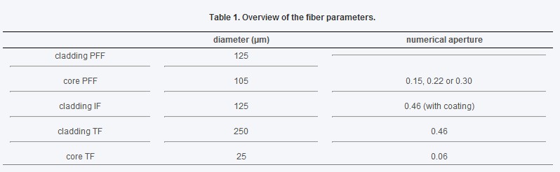
What is fiber laser? The world’s first laser beam is produced in 1960 by the use of flashbulb stimulating ruby crystalline grain. Limited by the thermal capacity of the grain, the pulsed beams is short and the frequency is very low. Although the instantaneous pulse peak can reach up to 106W, it still belongs to low energy output.
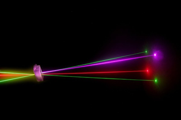
fiber laser 1

Source:tamu.edu

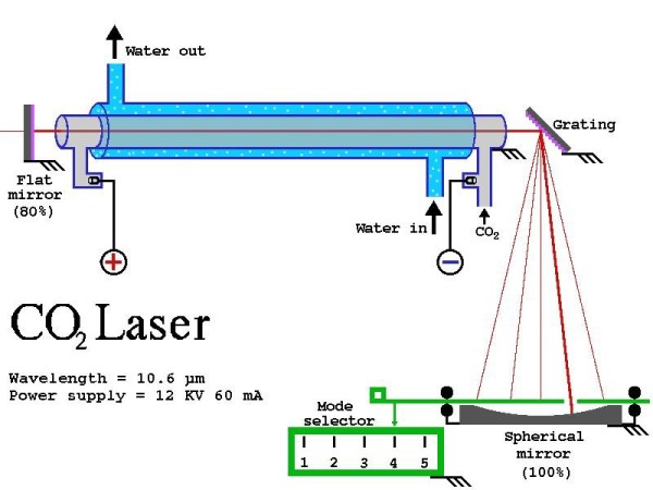
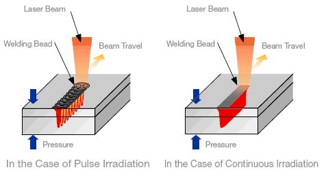
Laser technology adopts the beams of light generated by the reflection of laser from polariscope and congregates the beams in focusing device to generate beams with enormous energy. Once the focus is approaching, the workpieces will be melt or vapored in some milliseconds. This opens up a new welding application domain for high power CO2 and high power YAG laser. The key of laser welding equipment is high power laser, including solid laser and gas laser. Solid laser is the so called Nd:YAG laser. Nd is a rare earth elements and YAG represents Yttrium Aluminum Garnet, with similar crystal structure as ruby. The wavelength of Nd:YAG laser is 1.06μm. It can produce beam transmitted by fiber, so it can simplify beam delivery system, which is suitable in flexible manufacturing systems and remote working as well as high welding precision workpieces. Nd:YAG laser of 3-4 KW output is commonly used in automobile industry. Gas laser is the so-called CO2 laser. Its working medium is molecule gases which can generate iraser of 10.6μm in average. It can work continuously and output very high power; the standard laser power is between 2-5 KW.

The major traits of laser welding are as following:

  1. The welding is fast and deep with little deformation.
  2. It can work in room temperature and disparity conditions with simple equipment and device. For example, the laser beam will not offset; laser welding can be really carried out in vacuum, air or any gas environment, or even through glass or any transparent material.
  3. It can weld refractory materials as titanium and quartz and anisotropic materials with good effects.
  4. When welding, depth-to-width ratio can reach to 5:1 and the highest can reach up to 10:1.
  5. It can applied in microwelding. Slight flare can be generated by focused laser beams which can positioning precisely and be applied in mass automatic production of micro and small workpieces’ installation and welding.
  6. It is flexible in welding areas that is difficult to access. Especially in recent years, the adoption of optical fiber transmission in YAG laser processing technology has greatly promoted the popularization and application of laser welding technology.
  7. Beam split is easy to be realized by time and space and multiple beam can be processed all at once, providing conditions for more precise welding.

However, there are some limits of laser welding:

  1. It requires high assembly accuracy for weld and it should has no obvious deviation of beam on workpieces. It is because that the flare is too small and the welding line is too narrow. If the assembly accuracy and beam position cannot meet the requirements, it is easy to make weld defect.
  2. The cost and initial investment on laser and the relevant systems are high.

fiber laser 2

Resource : avio

DK Photonics – www.dkphotonics.com  specializes in designing and manufacturing of high quality optical passive components mainly for fiber laser applications such as 1064nm high power isolator, Cladding Power Stripper, Multimode High Power Isolator, pump combiner,1064nm Band-pass Filter,(6+1)X1 Pump and Signal Combiner, PM Circulator, PM Isolator, optical Coupler. More information, please contact us.


The Comparative Between Fiber Laser Cutting Machine and CO2 Cutting Machine

Cutting is one of the most widely applied laser processing techniques. Fiber laser and CO2 laser are the most commonly used laser cutting equipment. It is necessary for users to have a knowledge of the advantages and disadvantages of both the two ways of cutting.

CO2 laser

Source : fe.infn

Wavelength of fiber laser is 1.06μm and Wavelength of CO2 laser is 10.6μm. Both are infrared light and can be absorbed by material so that they can be applied in Industrial material processing. Fiber laser is unable to be applied in non-metal cutting, such as wood, plastic, leather and ramie cotton fabric. In case of non-metal cutting, CO2 laser is the only choice. But CO2 laser cannot cut copper products, including brass and red copper. Because copper is highly reflective material for CO2 laser, laser will be reflected instead of absorbed by copper, which can cause harm.

Laser is evaluated by integrated index as cutting speed, drilling efficiency and section quality.

Fiber laser has an advantage in cutting thin plate, especially for thickness under 3mm. Its maximum cutting speed ratio can reach to 4:1 and 6mm is critical thickness for the two kinds of lasers. When it is thicker than 6mm, fiber laser shows no preferential; as the thickness increases, CO2 laser shows preferential gradually but not outstandingly. Generally speaking, fiber laser has an advantage in cutting speed.

Drilling efficiency:

Before cutting, laser beam should penetrate workpiece. Fiber laser needs more time in drilling than CO2 laser. Take 3KW optical fiber laser and CO2 laser as an example, The latter saves 1 second in drilling 8mm carbon steel; and 2 seconds in 10mm drilling. As thickness grows, CO2 laser will save more time.

Fiber laser

Source : nufern

Section quality:

Section quality usually means the roughness (surface perfection) and perpendicularity.

When cutting steel plate under 3mm, section quality of fiber laser is worse then CO2. As thickness grows, the difference becomes more obvious.

In addition, carbon steel plate has high absorptivity on fiber laser energy, so it has shortcoming in cutting holes (aperture < panel thickness).

The above comparison will help users make a reasonable choice. The cutting speed of the two lasers is equally matched. Fiber laser is inferior to Co2 laser in section quality and drilling efficiency. There is no quick answer to which is better. They both have advantages and disadvantages in specific application demands.

By the way, laser cutting precision has nothing to do with the adoption of lasers. It is determined by machine positioning precision, resetting precision and consistency of kerf width. Fiber laser has narrower kerf than CO2. Kerf width doesn’t affect precision of the parts either, since it can be offset by cutting gap compensation.

DK Photonics – www.dkphotonics.com  specializes in designing and manufacturing of high quality optical passive components mainly for fiber laser applications such as 1064nm high power isolator, Cladding Power Stripper, Multimode High Power Isolator, pump combiner,1064nm Band-pass Filter,(6+1)X1 Pump and Signal Combiner, PM Circulator, PM Isolator, optical Coupler. More information, please contact us.

Ultrafast laser pulses induce atoms in gold nanodisks to vibrate

In a study that could open doors for new applications of photonics from molecular sensing to wireless communications, Rice University scientists have discovered a new method to tune the light-induced vibrations of nanoparticles through slight alterations to the surface to which the particles are attached.

In a study published online this week in Nature Communications, researchers at Rice’s Laboratory for Nanophotonics (LANP) used ultrafast laser pulses to induce the atoms in gold nanodisks to vibrate. These vibrational patterns, known as acoustic phonons, have a characteristic frequency that relates directly to the size of the nanoparticle. The researchers found they could fine-tune the acoustic response of the particle by varying the thickness of the material to which the nanodisks were attached.

“Our results point toward a straightforward method for tuning the acoustic phonon frequency of a nanostructure in the gigahertz range by controlling the thickness of its adhesion layer,” said lead researcher Stephan Link, associate professor of chemistry and in electrical and computer engineering.

Rice University researchers (clockwise from front) Man-Nung Su, Wei-Shun Chang and Fangfang Wen discovered a new method to tune the light-induced vibrations of nanoparticles through slight alterations to the surface to which they are attached.

Light has no mass, but each photon that strikes an object imparts a miniscule amount of mechanical motion, thanks to a phenomenon known as radiation pressure. A branch of physics known as optomechanics has developed over the past decade to study and exploit radiation pressure for applications like gravity wave detection and low-temperature generation.

Link and colleagues at LANP specialize in another branch of science called plasmonics that is devoted to the study of light-activated nanostructures. Plasmons are waves of electrons that flow like a fluid across a metallic surface.

When a light pulse of a specific wavelength strikes a metal particle like the puck-shaped gold nanodisks in the LANP experiments, the light energy is converted into plasmons. These plasmons slosh across the surface of the particle with a characteristic frequency, in much the same way that each phonon has a characteristic vibrational frequency.

The study’s first author, Wei-Shun Chang, a postdoctoral researcher in Link’s lab, and graduate students Fangfang Wen and Man-Nung Su conducted a series of experiments that revealed a direct connection between the resonant frequencies of the plasmons and phonons in nanodisks that had been exposed to laser pulses.

“Heating nanostructures with a short light pulse launches acoustic phonons that depend sensitively on the structure’s dimensions,” Link said. “Thanks to advanced lithographic techniques, experimentalists can engineer plasmonic nanostructures with great precision. Based on our results, it appears that plasmonic nanostructures may present an interesting alternative to conventional optomechanical oscillators and high power isolator

Chang said plasmonics experts often rely on substrates when using electron-beam lithography to pattern plasmonic structures. For example, gold nanodisks like those used in the experiments will not stick to glass slides. But if a thin substrate of titanium or chromium is added to the glass, the disks will adhere and stay where they are placed.

“The substrate layer affects the mechanical properties of the nanostructure, but many questions remain as to how it does this,” Chang said. “Our experiments explored how the thickness of the substrate impacted properties like adhesion and phononic frequency.”

Link said the research was a collaborative effort involving research groups at Rice and the University of Melbourne in Victoria, Australia.

“Wei-Shun and Man-Nung from my lab did the ultrafast spectroscopy,” Link said. “Fangfang, who is in Naomi Halas’ group here at Rice, made the nanodisks. John Sader at the University of Melbourne, and his postdoc Debadi Chakraborty calculated the acoustic modes, and Yue Zhang, a Rice graduate student from Peter Nordlander’s group at Rice simulated the optical/plasmonic properties. Bo Shuang of the Landes’ research group at Rice contributed to the analysis of the experimental data.”

The research was supported by the Robert A. Welch Foundation and the Department of Defense’s Multi-University Research Initiative. Additional co-authors include Zhang, Shuang, Nordlander and Halas, all of Rice; and Chakraborty and Sader, both of the University of Melbourne in Victoria, Australia.

About DK Photonics

DK Photonics – www.dkphotonics.com  specializes in designing and manufacturing of high quality optical passive components mainly for fiber laser applications such as 1064nm high power isolator, Cladding Power Stripper, Multimode High Power Isolator, pump combiner,1064nm Band-pass Filter,(6+1)X1 Pump and Signal Combiner, PM Circulator, PM Isolator, optical Coupler. More information, please contact us.

China laser innovation awards program now accepting nominations

The 2015 Ringier Technology Innovation Awards – Laser Industry is now open for applications up until January 4, 2015.

Now in its second year, the Awards consist of six categories: Lasers, Laser Systems for Production Engineering (Laser Cutting Systems, Laser Engraving Systems, Laser Marking Systems, and Laser Welding Systems), Laser System Components, System Peripherals of Laser Production Engineering, Optical Materials and Components, and 3D Printing. Only new products and solutions launched during 2013-2015 in the China market are eligible to enter the Awards selection process.

Following the entry and nomination stage, online peer voting and expert judging will take place January 9-25, 2015. Industry experts, including Dichen Li, Ph.D., Changjiang Professor, Xi’an Jiaotong University; Xiahui Tang, Professor, National Engineering Research Center For Laser Processing; Youliang Wang, Chairman, Laser Processing Committee of China Optical Society; Xiao Zhu, Chairman, Wuhan Laser Association of Optics Valley of China; and Qingmao Zhang, Vice Chairman, Laser Processing Committee of China Optical Society, will be among the independent panel of judges. Winners will be announced at the Awards ceremony on March 18, 2015, to coincide with Laser World of PHOTONICS 2015 in Shanghai, when all the winners, judges, industry professionals, and media will be present.

Organized by Industrial Laser Solutions China, Ringier Trade Media, and supported by Industrial Laser Solutions, these Awards are presented to a select group of innovators each year in China. The purpose of the Awards is to encourage, acknowledge, and reward those individuals and companies who have introduced and developed a new idea, a new methodology, a new product or a new technology for manufacturing production efficiency, cost-effectiveness, and user convenience, which might result in energy saving and more responsible clean manufacturing in the laser industry.

The Ringier Technology Industry Awards Series have been established since 2006 and cover nine different industries. They are recognized as being the most honest, transparent, and fairest of such Industry Awards in China. Nominations are open to all and the final selections are made by the panel of independent judges based solely on merit.


DK Photonics – www.dkphotonics.com  specializes in designing and manufacturing of high quality optical passive components mainly for fiber laser applications such as 1064nm high power isolator, Cladding Power Stripper, Multimode High Power Isolator, pump combiner,1064nm Band-pass Filter,(6+1)X1 Pump and Signal Combiner, PM Circulator, PM Isolator, optical Coupler. More information, please contact us.

Pump and signal combiner for bi-directional pumping of all-fiber lasers and amplifiers(7)

Pump and signal combiner for bi-directional pumping of all-fiber lasers and amplifiers(7)

5. Simulations and results for a multi pump port configuration

So far, the modeling results consider a TF with only a single pump port. However, for monolithic high power fiber laser and amplifier systems, it is often required to provide multiple pump ports due to the limited output power of available fiber coupled pump diodes and the efforts to develop laser systems with redundancy. Thus, in this section, we investigate the impact of multiple pump ports on the coupling efficiency and the loss mechanism. The setup of each pump combiner is identical to the description in Section 2 (see Fig. 1), but with several additional ports placed around the cladding of the TF, leading to a fiber bundle. A schematic of a fiber combiner with multiple pump ports is shown in Fig. 7

Pump and signal combiner for bi-directional pumping of all-fiber lasers and amplifiers(7)

Fig. 7 Fiber combiner with multiple pump ports, PFF: pump feeding fiber with a piece of coreless intermediate fiber (IF) as described in Fig. 1, TF: target fiber, TP: transmitted power.

5.1 Simulations of the pump coupling efficiency

The experiments and simulations in Section 4 showed that for a pump combiner with a single pump port, a TL of 20 mm and a TR of 6 yields an excellent coupling efficiency in the range of 95%. In comparison, for a fiber band pass filter with multiple pump ports, the simulations for a TL of 20 mm (Fig. 8(a)

Pump and signal combiner for bi-directional pumping of all-fiber lasers and amplifiers(7)-2

Fig. 8 Simulated coupling efficiency for a pump combiner with up to 6 pump ports for (a) a TL of 20 mm and (b) a TL of 10 mm for a pump light input NA of 0.22.

) revealed that the pump coupling efficiency of the combined pump power depends on the number of pump ports and significantly on the choice of the TR. In the simulations the input pump light NA of the PFFs was 0.22. In general, it can be seen that the pump coupling efficiency decreases with each additional pump port. A lower TR yields a greater decrease of the pump coupling efficiency with each additional pump port than a higher TR. In the case of a TL of 20 mm and a TR of 2.5, the theoretically obtainable pump coupling efficiency of almost 90% decreases to 73%, if the number of pump ports increases from 1 to 6. However, as already mentioned, the increasing losses due to additional pump ports can be reduced with increasing TR. In Fig. 8(a) it can be clearly observed that for 6 pump ports and a TR of 6, a pump coupling efficiency of 90.2% can be achieved. For a TR higher than 6, it is not possible to achieve a significant improvement in pump coupling efficiency for multiple pump ports by increasing of the TR.

For a single pump port configuration it is already known that the pump coupling efficiency decreases with shorter TLs at constant TRs (Fig. 2(a)). However, for multiple pump ports a reduction of the TL leads to the advantage that the pump coupling efficiency of the combined pump power decreases less with each additional pump port, especially at lower TRs. The simulation results for a TL of 10 mm instead of a TL of 20 mm are presented in Fig. 8(b). A comparison of Fig. 8(a) and 8(b) shows: If the number of pump ports is increased from 1 to 6 at a TR of 2.5, the pump coupling efficiency experiences a decrease of 16.9 and 11.2% for a TL of 20 and 10 mm, respectively. Although the total power losses for a TL of 10 mm are higher than for a TL of 20 mm, the example reveals, that the decrease of the pump coupling efficiency due to additional pump ports can be reduced by using shorter TLs.

Besides having less available combined pump power, the additional pump power losses generated in comparison to a fiber combiner with a single pump port, corresponds to an enhanced risk of damaging the component due to additional thermal load. Hence, the loss mechanism for a fiber combiner with multiple pump ports needs to be investigated in more detail.

About DK Photonics

DK Photonics – www.dkphotonics.com  specializes in designing and manufacturing of high quality optical passive components mainly for fiber laser applications such as 1064nm high power isolator, Cladding Power Stripper, Multimode High Power Isolator, pump combiner,1064nm Band-pass Filter,(6+1)X1 Pump and Signal Combiner, PM Circulator, PM Isolator, optical Coupler. More information, please contact us.

Industrial Fiber Laser Introduction and Global Market Forecast –DK Photonics

The Global Industrial Fiber Laser market to grow at a CAGR of 21.4% over the period 2013-2018

Fiber lasers contain the active gain medium, which is an optical fiber integrated with rare earth elements such as erbium and ytterbium. Unlike conventional gas lasers, a fiber laser uses part of the fiber as the resonating cavity, where the laser action takes place to generate laser beams , Fiber lasers are preferred over other lasers such as CO2 lasers and excimer lasers, primarily because they are more reliable, efficient, robust, and portable, and easier to operate than other lasers.

Fiber lasers used for industrial applications such as cutting, welding, marking, and engraving in the Manufacturing, Semiconductor, and Automotive industries are referred to as industrial fiber lasers. Moreover, due to their superior performance, compact size, high output power, low cost of ownership, durability, and eco-friendly attributes, industrial fiber lasers are being adopted at a significant rate. They also eliminate the mechanical adjustments and high maintenance costs that are necessary with other lasers.

Increased R&D spending by vendors to gain a competitive advantage over other players in the market is one key trend in this market. Vendors are increasingly investing in their R&D division to provide better functionality and to meet the unsatisfied requirements of consumers. R&D investments have enabled vendors to capture a significant market share and gain a competitive edge over other vendors in the Global Industrial Fiber Laser market.

According to the report, one major driver of the market is the increased adoption of fiber lasers because of their superior attributes. These lasers used for industrial applications are gaining more significance because they exhibit excellent light properties.

Further, the report states that one of the key challenges that the market faces is the uncertainty regarding the lifespan of fiber lasers. Despite their existence in the industry for more than 10 years, the lifespan fiber lasers are not definite.


DK Photonics – www.dkphotonics.com  specializes in designing and manufacturing of high quality optical passive components mainly for fiber laser applications such as 1064nm high power isolator, Cladding Power Stripper, Multimode High Power Isolator, pump combiner,1064nm Band-pass Filter,(6+1)X1 Pump and Signal Combiner, PM Circulator, PM Isolator, optical Coupler. More information, please contact us.

Pump and signal combiner for bi-directional pumping of all-fiber lasers and amplifiers(6)

Pump and signal combiner for bi-directional pumping of all-fiber lasers and amplifiers(6)

4.4 Experimental results

In order to verify the simulations, two fiber combiners with a single pump port based on the setup described in Section 2 were developed. For the first combiner an IF with a low TR of 2.6 and a short TL of 9.5 mm was fabricated. In the case of the second combiner the TR and the TL were increased to 6.7 and 18 mm, respectively. For both combiners the geometrical dimensions of the obtained tapered IFs were measured with an optical microscope. After completion of the fabrication, both combiners were optically characterized. Therefore, each PFF (pump port) with a NA of 0.15 was connected to a pump diode (Oclaro BMU25) with a pigtail fiber delivering a maximum output power of ~25 W at a wavelength of 976 nm. The delivery fiber of the pump diode had parameters identical to the PFF.

The experimental results for the first fiber combiner are shown in Fig. 6(a)

getImage

Fig. 6 Coupled and transmitted power measured for a fiber combiner with one pump port with (a) a TL of 9.5 mm (TR of 2.6) and (b) a TL of 18 mm (TR 6.7), * ratio of coupled or transmitted power to total diode power in percent.

. Due to the low TR of 2.6, an experimental pump coupling efficiency of only 74% was achieved. The residual pump power was almost completely measured as TP, with a power fraction of 25.3%. The simulations for the coupled as well as the TP show good agreement with the experimental results, and confirm that in the case of a low TR of 2.6, the pump power is only divided into coupled power and TP. In Fig. 6(a) it can be seen that in the simulations the sum of the coupled and TP is 99.9%, corresponding to 0.1% of pump light rays not detected in the simulations. This can be treated as a simulation error. That the measured sum of coupled pump power and TP is only 99.3% can be explained by measurement uncertainties, marginal splice losses and additional power losses in the fiber component caused by dust particles. Since the thermal load of this fiber combiner design is negligible it would be feasible to couple several kW of pump power, but with the disadvantage of a moderate coupling efficiency of about 75% and consequently a undesirable overall efficiency for high power laser system.

For the second fiber combiner, depicted in Fig. 6(b), a higher pump coupling efficiency of 95.2% (96.0% in simulation) was measured as compared to the first combiner presented in Fig. 6(a) due to the increase in TR and TL. Following the simulations the residual pump power of 4% can be divided into TP, PCT and PAA with 2.4%, 0.6% and 0.9%, respectively. Again, the missing pump power of 0.1% was associated with an error owing to undetected power in the simulations. For the TP a fraction of 2.3% was measured and shows very good agreement with the simulation (2.4%), i.e. more than 50% of the total power loss was TP. This fraction of power represents no risk for damage to the fiber component. Due to the excellent agreement between simulation and experiment, the simulated PCT-fraction of only 0.6% is a good value for an estimate of the thermal load of the coating of the TF. Based on the simulations and experiments an error of less than 1% of the pump input power can be assumed for the PCT-fraction.

Unfortunately, the power fractions PAA and PCT are difficult to measure and therefore could not be experimentally determined. In future work an indirect measurement of PCT will be realized by measuring the coating temperature of the CWDM Module. In summary, the simulations describe the coupling efficiency as well as the fraction of TP very well, and thus, serve as a very good estimation for the fraction of PCT and PAA.

DK Photonicswww.dkphotonics.com  specializes in designing and manufacturing of high quality optical passive components mainly for telecommunication, fiber sensor and fiber laser applications,such as PLC Splitter, WDM, FWDM, CWDM, DWDM, OADM,Optical Circulator, Isolator, PM Circulator, PM Isolator, Fused Coupler, Fused WDM, Collimator, Optical Switch and Polarization Maintaining Components, Pump Combiner, High power isolator, Patch Cord and all kinds of connectors.

Fiber Optic Sensors Global Market Forecast- DK Photonics

According to ElectroniCast, the combined use of Continuous Distributed and Point fiber optics sensors will reach $4.33 Billion in 2018…

Aptos, CA (USA) – February 14, 2014 —ElectroniCast Consultants, a leading market/technology forecast consultancy, today announced the release of their market forecast and analysis of the global consumption Fiber Optic Point Sensors and Continuous Distributed Fiber Optics Sensor systems.

According to ElectroniCast, the consumption value is forecast to increase at an impressive 18% per year from $1.89 billion in 2013 to $4.33 billion in 2018.  Market forecast data refers to consumption for a particular calendar year; therefore, this data is not cumulative data.

Continuous Distributed fiber optic sensor systems involve the optic fiber with the sensors embedded with the fiber.  ElectroniCast counts each Point fiber optic sensor as one unit; however, the volume of Distributed Continuous fiber optic sensors is based on a complete optical fiber line and associated other components, which are defined as a system.

The use of Distributed Continuous fiber optic sensors in the Military/Aerospace/Security application category maintains the lead in 2014, followed by the Petrochemical/ Energy sector.  The Civil Engineering/Construction sector, which includes continuous fiber sensors used in Structural Health Monitoring (SHM) as well as other concerns in buildings, bridges, tunnels, towers, and other structures, is also forecast for strong growth.  Inspection and quality control frequently constitute the largest portion of production costs for many industries.

“There is a growing need for improved measurement solutions, which offer higher precision, speed and accuracy and provide better in-process measurement of moving objects, resulting in lower costs for better products.  Relatively speaking, the Manufacturing/ Factory segment tends to favor point sensors instead of distributed fiber systems,” stated Stephen Montgomery, Director of the Fiber Optics Components group at ElectroniCast Consultants.

“The Biomedical/ Science sector is a relatively minor user of Distributed Continuous fiber optic sensors, in terms of consumption value, since the length of optical fiber is (very) short versus the other applications; therefore the average selling prices for the distributed continuous fiber optic sensor systems are low compared to the larger (longer length of optical fiber) distributed continuous fiber optic sensor systems used in other applications. The consumption value of Distributed Continuous fiber optic sensor systems is forecast to grow at 23% per year from $1.099 billion in 2013 to $3.096 billion in the year 2018,” Montgomery added.

DATA FIGURE

According to ElectroniCast, the consumption value of fiber optic sensors (continuous distributed systems + Point-types) will increase from $1.89 billion in 2013 to $4.33 billion in 2018.

Fiber Optic Sensor Global Consumption Market Forecast

Point vs. Distributed Continuous
(Value Basis, $Million
)

Fiber Optic Sensor Global Consumption Market Forecast


Note: Market forecast data refers to consumption for a particular calendar year; therefore, this data is not cumulative data.

DK Photonicswww.dkphotonics.com  specializes in designing and manufacturing of high quality optical passive components mainly for telecommunication, fiber sensor and fiber laser applications,such as PLC Splitter, WDM, FWDM, CWDM, DWDM, OADM,Optical Circulator, Isolator, PM Circulator, PM Isolator, Fused Coupler, Fused WDM, Collimator, Optical Switch and Polarization Maintaining Components, Pump Combiner, High power isolator, Patch Cord and all kinds of connectors.

Pump and signal combiner for bi-directional pumping of all-fiber lasers and amplifiers(4)

4. Simulations and experiments for a fiber combiner with a single pump port

The ray tracing simulations were carried out with the commercially available software Zemax (Radiant Zemax, LLC) in the non-sequential mode. Detailed information about ray tracing in tapered cylindrical fibers can be found in Ref [16] and [17]. The ray tracing method is applicable due to the large cross sections of the employed fibers compared to the applied wavelength of 976 nm. The 3-dimensional simulation model of the fiber combiner was based on the setup depicted in Fig. 1 with the approximation of a parallel fiber arrangement of the IF and TF. For the PFF a fully filled condition was always assumed, meaning that all possible pump light rays, independent of the NA and the transversal position in the fiber core, carry equal power. For the geometrical shape of the taper in the longitudinal direction, a simplified linear shape was assumed in the simulations, instead of the measured parabolic shape. As already mentioned, the FL was set to 1.99. 

4.1 Simulations of the pump coupling efficiency

The pump coupling efficiency in dependence of the converging taper length (TL) and the taper ratio (TR) of the IF for a 1064nm high power isolator with an NA of 0.22 is depicted in Fig. 2(a)

pump coupling efficiency

Fig. 2 (a) Pump coupling efficiency (CE) with respect to the taper ratio (TR) and the converging taper length (TL) and (b) a comparison of the pump coupling efficiencies without intermediate fiber (IF) and with IF for different fiber parameters, IF Ø: IF cladding diameter.

. The simulations show that an increasing TL leads to higher coupling efficiencies at a constant TR. For example at a constant TR of 6 a TL of 5 mm leads to a theoretical maximum pump coupler coupling efficiency of 86%, whereas for a TL of 20 mm 96.4% were calculated. Furthermore, Fig. 2(a) shows that the TR can be reduced, if the TL is increased to maintain a certain coupling efficiency level. For instance, for a TL of 20 mm, a coupling efficiency of 85% can already be obtained at a TR of 2 instead of a TR of 5.5 at a TL of 5 mm. The improved coupling behavior at longer TLs can be explained by the increasing number of bounces of the pump light rays at the lateral surface of the converging taper portion. Hence, for shorter TLs it is necessary to taper more than for longer TLs in order to compensate for the shorter interaction length of the converging taper portion with the TF. The maximum theoretically obtainable pump coupling efficiency was limited to 97.3% due to different loss mechanisms, which will be discussed in Section 4.3.

In the following section we discuss the impact of the intermediate fiber on the pump coupling efficiency and the taper parameters. Thus, for comparison the fiber combiner was also simulated without the IF, which means that the tapered PFF was directly connected to the TF, assuming the same FL and also a NA of 0.22. Figure 2(b) illustrates that the coupling efficiency can be increased and the TR reduced, if an IF is inserted between the PFF and the TF. For a TR of 2.5 at a TL of 20 mm the coupling efficiencies with and without IF are 61.2% and 90.1%, respectively. The moderate coupling efficiencies without the employment of an IF at low TR can be explained by the presence of a depressed refractive index of the cladding of the PFF, blocking the power transfer from the IF to the TF, as already discussed in Section 2. Thus, without IF, the pump light rays with a low NA cannot escape from the core of the PFF, and a considerable fraction of power will be transmitted via the diverging taper portion. A further increase of the pump light NA, due to the increase of the TR up to 10 at a TL of 20 mm for the PFF and the IF, results in a successive approximation of the Polarization Maintaining Optical Circulator efficiencies. However, even at a TR of 10 and a TL of 20 mm (with IF) a 2.5% higher pump coupling efficiency can be obtained. That means for a hypothetical available input pump power of 1 kW, a reduction in power loss of 25 W can be essential to prevent thermal damage of the fiber combiner. Additionally, it must be taken into account that a TR of 10 corresponds to a considerable reduction of the mechanical stability due to the fiber diameter tapering from 125 µm to 25 µm. Furthermore, Fig. 2(b) clearly shows that the insertion of an IF with a TL of 10 mm already yields better pump coupling efficiencies than a PFF with a TL of 20 mm, especially for low TR.

A further increase of the pump coupling efficiency up to 97.8% can be realized by inserting an IF with a TL of 20 mm and diameter of 105 µm, which is perfectly adapted to the core diameter of the PFF, and thus, no pump brightness loss occurs. Note that for all of the following simulations and experiments, we only used the fiber component containing an inserted IF with a cladding diameter of 125 µm.

4.2 Simulations for the impact of the pump light input NA on the pump coupling efficiency

In the next simulation step we figure out, how the pump coupling efficiency changes with the pump light input NA depending on TR and TL. For these simulations three types of PFFs with a core NA of 0.15, 0.22 and 0.30 were investigated, assuming for each PFF a fully filled pump light condition. The TR was considered in the range from 1 to 10 at a TL of 5 mm

Simulations for the impact of the pump light input NA on the pump coupling efficiency

Fig. 3 Pump coupling efficiency with respect to the taper ratio at a converging taper length of (a) 5 mm and (b) 20 mm for a PFF with a pump light input NA of 0.15, 0.22 and 0.30.

) and 20 mm (Fig. 3(b)). From both figures it can be seen that at lower TRs the coupling efficiency increases with NA, since the pump light rays with a higher NA have more bounces with the lateral surface of the converging taper portion. However, the pump coupling behavior changes with increasing TR, since a TR of much higher than 2 leads to pump light rays with a NA far above 0.46, which cannot couple into the TF, if the TL is too short. The occurring pump power losses will be discussed in Section 4.3. E.g., for a low TL of 5 mm and a TR of 7 the coupling efficiency for an input NA of 0.15 was simulated to be 10% higher than for an input NA of 0.30. In contrast, with a longer TL of 20 mm the coupling efficiency seems to be less sensitive to variations of the pump light input NA. Thus, it appears that for the combiner design, the pump coupling efficiency should not be significantly influenced by the pump light input NA in the range of 0.15 to 0.30, if a sufficient TL is considered.

If the pump light input NA gets closer to the NA of the TF of 0.46, it can be advantageous to use a straight IF portion in addition to the converging taper to obtain a highly efficient pump light transfer into the TF as described in Ref [13]. An alternative approach to the straight IF portion is an increased TL, i.e. for a pump light input NA of 0.46 a theoretical pump coupling efficiency of about 90% can be achieved, if the TL is at least 40 mm.

Pump and signal combiner for bi-directional pumping of all-fiber lasers and amplifiers(3)

3. Fabrication

The IF was fusion spliced to the DK Photonics with a filament splicing system (Vytran FFS-2000). A hydrogen-oxygen micro-flame was applied as heat source for tapering and lateral splicing of the IF. The working temperature for the tapering as well as the weak lateral splicing process of the IF was not measured but it can be assumed to be between the annealing and softening point of fused fiber coupler. The temperature adjusting was controlled by variation of the vertical distance between the fiber and the flame. Two precisely controlled motor stages were used to allow accurate alignment and tapering of the fiber(s). The heat source was placed at a fixed position in the center between the two motor stages. Each IF was individually tapered with a pulling speed of about 40 µm/s per motor stage and a fiber tension of about 10−2 N. After tapering, the IF was once twisted around the TF, which ensures that the converging taper portion remain in contact during lateral fusing. In case of a fiber combiner with several pump ports (see Section 5), the IFs were also individually tapered but simultaneously twisted around the TF. The final lateral fusion process along the converging taper portion was carried out at temperatures which allow sufficient softening of the tapered IF(s) and only slightly softening of the TF resulting in a weak fused component without any thermally induced damage of the core of the TF.

4. Simulations and experiments for a fiber combiner with a single pump port

The ray tracing simulations were carried out with the commercially available software Zemax (Radiant Zemax, LLC) in the non-sequential mode. Detailed information about ray tracing in tapered cylindrical fibers can be found in Ref [16] and [17]. The ray tracing method is applicable due to the large cross sections of the employed fibers compared to the applied wavelength of 976 nm. The 3-dimensional simulation model of the fiber combiner was based on the setup depicted in Fig. 1 with the approximation of a parallel fiber arrangement of the IF and TF. For the PFF a fully filled condition was always assumed, meaning that all possible pump light rays, independent of the NA and the transversal position in the fiber core, carry equal power pump combiner. For the geometrical shape of the taper in the longitudinal direction, a simplified linear shape was assumed in the simulations, instead of the measured parabolic shape. As already mentioned, the FL was set to 1.99. Table 1 shows a summary of the fiber parameters used for simulations:

shows a summary of the fiber parameters used for simulations:
shows a summary of the fiber parameters used for simulations