How much do you know about CWDM Multiplexer and DWDM Multiplexer

CWDM multiplexer and DWDM multiplexer are two main products of WDM multiplexer. The full name of WDM, CWDM and DWDM are wavelength division multiplexing, coarse wavelength division multiplexing and dense wavelength multiplexing respectively. How much do you know about them? If you have no idea, the following introduction will help you a lot.

In the very first place, let’s get to know what the WDM is. Based on a single fiber optic transmission, many optical signals that are loaded with information and have different wavelengths can be synthesized into one single beam by WDM multiplexer. Then, a special communication technology will be adopted to separate those optical signals at the receiving terminal. On the basis of WDM technique, the CWDM device and DWDM device are two popular products in the current market.

CWDM device

When it comes to the CWDM multiplexer, first of all, it provides service for metropolitan area network access layer, whose working principle is in line with WDM multiplexer. However, it simplifies the structure largely. For example, the filter film layer number of CWDM is just 50, while the WDM is as many as 200 layers. That is to say, the rate of finished products has been improved and the cost has been reduced largely. Besides low cost, the CWDM device is also advantageous in small volume, small power consumption, convenient maintenance and large transmission capacity. The laser device in the system doesn’t need semiconductor refrigerator and temperature controller, which can lessen the power consumption obviously. However, the CWDM also has shortcomings. For instance, developing and simplifying the optical transceiver module and optical component is urgent to be solved.

DWDM device

As to the DWDM multiplexer, comparatively speaking, it makes the best use of fiber-optical bandwidth and enhances the message capacity of cellular system, which is well-known for simple dilatation and stable performance. Integrated system and open system are two dominant application systems of DWDM multiplexer, which are based on different wavelength conversion technologies. No matter which system is adopted, the free-running 1510nm wavelength will be chosen to carry OSC or optical supervisory channel so as to transmit information. Such an OSC is a comparatively independent subsystem, which offers maintenance and management information.

The last question is what advantages WDM technique has when compared with traditional transmission methods. Generally speaking, it includes such aspects as making best use of low-loss wave band, transmitting several optical signals in one optical fiber, good flexibility, low investment cost, excellent system reliability and fast and convenient recovery.


Tags: CWDM Multiplexer, DWDM Multiplexer,19″ rack mount chassis CWDM, ABS plastic box, CWDM MUX/DEMUX Module,  LGX CWDM Module,8CH CWDM Module, 16CH CWDM Module

Do you know these about CWDM Multiplexer and DWDM Multiplexer?

Do you know these about CWDM Multiplexer and DWDM Multiplexer?

Wavelength division multiplexing (WDM) is a technology or technique modulating numerous data streams, i.e. optical carrier signals of varying wavelengths (colors) of laser light, onto a single optical fiber. The goal of WDM is to have a signal not to interfere with each other. It is usually used to make data transmission more efficiently. It has also been proven more cost effective in many applications, such as WDM network applications, broadband network application and fiber to the home (FTTH) applications and so on. According to channel spacing between neighbored wavelengths, there are two main types of WDM, including Coarse WDM (CWDM) and Dense WDM (DWDM). Though both of them belong to WDM technology, they are quite different. Then, what are the differences between them? This paper will give you the answer.

Definition of CWDM

CWDM is a method of combining multiple signals on laser beams at various wavelengths for transmission along fiber optic cables, such that the number of channels is fewer than in DWDM but more than in standard WDM. “Course” means the channel spacing is 20nm with a working channel passband of +/-6.5nm from the wavelengths center. From 1270nm to 1610nm, there are 18 individual wavelengths separated by 20nm spacing.

Definition of DWDM

DWDM is a technology that puts data from different sources together on an optical fiber, with each signal carried at the same time on its own separate light wavelength. “Dense” refers to the very narrow channel spacing measured in Gigahertz (GHz) as opposed to nanometer (nm). DWDM typically uses channel spacing of 100GHz with a working channel passband of +/-12.5GHz from the wavelengths center. It uses 200GHz spacing essentially skipping every other channel in the DWDM grid. And it has also gone one step further using an Optical Interleaver to get down to 50GHz spacing doubling the channels’ capacity from 100GHz spacing.

CWDM vs DWDM

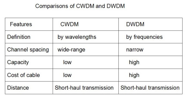
According to the content above, you will find some small differences between them. 16CH CWDM Module is defined by wavelengths and has wide range channel spacing. DWDM is defined by frequencies and has narrow channel spacing. What’s more, what other differences do they have?

Capacity of Data

In fiber optic network system, DWDM system could fit more than 40 different data streams in the same amount of fiber used for two data streams in a CWDM system. In some cases, CWDM system can perform many of the same tasks compared to DWDM. Despite the lower transmission of data through a CWDM system, these are still viable options for fiber optic data transmission.

Cost of Cable

CWDM system carries less data, but the cabling used to run them is less expensive and less complex. A DWDM system has much denser cabling and can carry a significantly larger amount of data, but it can be cost prohibitive, especially where there is necessary to have a large amount of cabling in an application.

Long-haul or Short-haul Transmission

DWDM system is used for a longer haul transmission through keeping the wavelengths tightly packed. It can transmit more data over a significantly larger run of cable with less interference. However, CWDM system cannot travel long distances because the wavelengths are not amplified, and therefore CWDM is limited in its functionality over longer distances. If we neeed to transmit the data over a very long range, DWDM system solution may be the best choice in terms of functionality of the data transmission as well as the lessened interference over the longer distances that the wavelengths must travel. As far as cost is concerned, when required to provide signal amplification about 100 miles (160km), CWDM system is the best solution for short runs.

According to the content above, maybe you have already understood some differences between CWDM and DWDM by the comparision of them from definition, capacity, cable cost and transmission distance etc. And here is also a figure of comparisons between CWDM and DWDM which may help you to consolidate your understanding of this paper.

CWDM Multiplexer and DWDM Multiplexer

Tags: 19″ rack mount chassis CWDM, ABS plastic box, CWDM MUX/DEMUX Module,  LGX CWDM Module,8CH CWDM Module, 16CH CWDM Module

Saving Your Fibers By Using CWDM Or DWDM Multiplier

Using a WDM(Wavelength Division Multiplexing) for expanding the capacity of the fiber to carry multiple client interfaces is a highly advisable way as the physical fiber optic cabling is not cheap. As WDM widely used you must not unfamiliar with it, it is a technology that combines several streams of data/storage/video or voice protocols on the same physical fiber-optic cable, by using several wavelengths (frequencies) of light with each frequency carrying a different type of data.

Two types of WDM architecture available: Coarse Wavelength Division Multiplexing (CWDM) and Dense Wavelength Division Multiplexing (DWDM). CWDM/DWDM multiplexer and demultiplexer and OADM (Optical Add-Drop Multiplexer) are common fit in with Passive. With the use of optical amplifiers and the development of the OTN (Optical Transport Network) layer equipped with FEC (Forward Error Correction), the distance of the fiber optical communication can reach thousands of Kilometers without the need for regeneration sites.

16-Ch CWDM Mux/Demux Module

CWDM

Each CWDM wavelength typically supports up to 2.5Gbps and can be expanded to 10Gbps support. The CWDM is limited to 16 wavelengths and is typically deployed at networks up to 80Km since optical amplifiers cannot be used due to the large spacing between channels. CWDM uses a wide spectrum and accommodates eight channels. This wide spacing of channels allows for the use of moderately priced optics, but limits capacity. CWDM is typically used for lower-cost, lower-capacity, shorter-distance applications where cost is the paramount decision criteria.

The CWDM Mux/Demux (or CWDM multiplexer/demultiplexer) is often a flexible plug-and-play network solution, which helps insurers and enterprise companies to affordably implement denote point or ring based WDM optical networks. CWDM Mux/demux is perfectly created for transport PDH, SDH / SONET, ETHERNET services over WDM, CWDM and DWDM in optical metro edge and access networks. CWDM Multiplexer Modules can be found in 4, 8 and 16 channel configurations. These modules passively multiplex the optical signal outputs from 4 too much electronic products, send on them someone optical fiber and after that de-multiplex the signals into separate, distinct signals for input into gadgets across the opposite end for your fiber optic link.

Typically CWDM solutions provide 8 wavelengths capability enabling the transport of 8 client interfaces over the same fiber. However, the relatively large separation between the CWDM wavelengths allows expansion of the CWDM network with an additional 44 wavelengths with 100GHz spacing utilizing DWDM technology, thus expanding the existing infrastructure capability and utilizing the same equipment as part of the integrated solution.

100GHz 8-Ch DWDM Mux/Demux Module

DWDM

DWDM is a technology allowing high throughput capacity over longer distances commonly ranging between 44-88 channels/wavelengths and transferring data rates from 100Mbps up to 100Gbps per wavelength.

DWDM systems pack 16 or more channels into a narrow spectrum window very near the 1550nm local attenuation minimum. Decreasing channel spacing requires the use of more precise and costly optics, but allows for significantly more scalability. Typical DWDM systems provide 1-44 channels of capacity, with some new systems, offering up to 80-160 channels. DWDM is typically used where high capacity is needed over a limited fiber resource or where it is cost prohibitive to deploy more fiber.

The DWDM multiplexer/demultiplexer Modules are made to multiplex multiple DWDM channels into one or two fibers. Based on type CWDM Mux/Demux unit, with optional expansion, can transmit and receive as much as 4, 8, 16 or 32 connections of various standards, data rates or protocols over one single fiber optic link without disturbing one another.

Ultimately, the choice to use CWDM or DWDM is a difficult decision, first we should understand the difference between them clearly.

CWDM vs DWDM

CWDM scales to 18 distinct channels. While, DWDM scales up to 80 channels (or more), allows vastly more expansion. The main advantage of CWDM is the cost of the optics which is typically 1/3rd of the cost of the equivalent DWDM optic. CWDM products are popular in less precision optics and lower cost, less power consumption, un-cooled lasers with lower maintenance requirements. This difference in economic scale, the limited budget that many customers face, and typical initial requirements not to exceed 8 wavelengths, means that CWDM is a more popular entry point for many customers.

Buying CWDM or DWDM is driven by the number of wavelengths needed and the future growth projections. If you only need a handful of waves and use 1Gbps optics, CWDM is the way to go. If you need dozens of waves, 10Gbps speeds, DWDM is the only option.


2~18CH CWDM MUX/DEMUX Module from DK Photonics

The key components in a WDM system are the optical wavelength multiplexer (MUX), and the de-multiplexer (DEMUX). In general, a CWDM (coarse WDM) MUX/DEMUX deals with small numbers of wavelengths, typically eight, but with large spans between wavelengths (spaced typically at around 20nm). A DWDM (dense WDM) MUX/DEMUX deals with narrower wavelength spans (as small as 0.8nm, 0.4nm or even 0.2nm), and can accommodate 40, 80, or even 160 wavelengths.

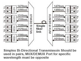
The one kind of DK Photonics LGX CWDM MUX/DEMUX modules are bi-directional passive optical multiplexers and de-multiplexers, allowing multiple optical signals at different wavelengths to pass through a single optical fiber strand.

simplex-bidi-transmission-cwdm-mux-demux

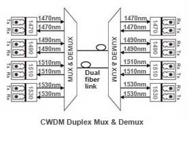
The second DK Photonics ABS CWDM MUX/DEMUX modules are duplex fiber link bi-directional multiplexers and de-multiplexers, allowing multiple optical signals’ at different wavelengths to pass through duplex optical fiber.

duplex-bidi-transmission-cwdm-mux-demux

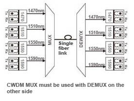
The last one kind is simplex directional CWDM MUX only or CWDM DEMUX only. The kind of mux and demux must be used with each other.

simplex-directional-transmission-cwdm-mux-demux

CWDM MUX/DEMUX solution lets operators make full use of available fiber bandwidth in local loop and enterprise architectures. Our CWDM MUX/DEMUX modules split up to 18 channels (20 nm spaced) to a single fiber. The standard packages are ABS Plastic Box, 19″ Rack Mount Chassis CWDM Mux/Demux  and LGX Metal Box Mux/Demux. No matter what kinds of connectors (such as FC, ST, SC, LC, etc.) are all available and we can also mix connectors on one device.

CWDM MUX+DEMUX 8 Channels (Dual Fiber) Module

DK Photonics offers a wide range of WDM (Wavelength Division Multiplexing) optical networking products that allow transport of any mix of services from 2Mbps up to 100Gbe over dark fiber and WDM networks providing for the entire set of the most demanding CWDM and DWDM network infrastructure needs.

2015-Fiber Optic Communication Collimators Market Forecast

Fiber optic collimator lens arrays are forecast with strong value-based growth rates of more than 30% per year (2014-2019)…

Aptos, CA (USA) – March 23, 2015 — ElectroniCast Consultants, a leading market research & technology forecast consultancy addressing the fiber optics communications industry, today announced the release of a new market forecast of the global market consumption and technology trends of small beam collimating lens assemblies in fiber optic communication (including telecommunication, datacom and cable TV) passive and active/integrated (hybrid) components/devices.

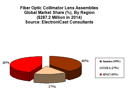
The market study covers single lens assemblies, 2-12 lens arrays, and arrays with more than 12 lenses. Both of the lens array categories are forecast with strong growth rates of more than 30% per year (2014-2019). Single lens fiber optic collimator assemblies held the global market share lead, with over 80% in 2014.

“Collimator lenses are used in a variety of photonic products; however this market study forecasts the use of micro-sized collimator lens assemblies, which are used specifically in optical communication components/devices(such as 8CH LGX CWDM Module). Fiber optic collimator lens assemblies serve as a key indicator of the growth of the fiber optic communication component industry,” said Stephen Montgomery, Director of the Fiber Optic Component group at the California-based consultancy.

ElectroniCast defines lens assemblies as “loose” lenses (one or more), which are attached to an optical fiber or fitted/attached into (or on) a planar waveguide/array substrates or other device(s), such as a ferrule, for the purpose of collimating light for optical fiber communication.

The global consumption of fiber optic collimator lens assemblies, which are used in commercial optical communication applications, reached $287.2 million in 2014, an increase of 8.7% over the previous year.

Consumption is based on the geographical (region) location where the lens assembly is first used into (the) higher-level component or module package; therefore, ElectroniCast forecasts that the Asia Pacific Region will hold the market share lead for most of the timeframe covered in the forecast period.  America, led by the United States, is forecast to remain in the 2nd-place market position until 2019.  Europe is forecast to maintain moderate-to-strong growth, as the region is steadily involved in value-added building (and use) of sub-assemblies and equipment.  Market forecast data in the ElectroniCast report refers to consumption (use) for a particular calendar year; therefore, this data is not cumulative data.

DK Photonicswww.dkphotonics.com  specializes in designing and manufacturing of high quality optical passive components mainly for telecommunication, fiber sensor and fiber laser applications,such as 1064nm High Power Isolator,1064nm Components, PM Components, (2+1)x1 Pump Combiner,Pump Laser Protector,Mini-size CWDM,100GHz DWDM,Optical Circulator,PM Circulator,PM Isolator,Fused Coupler,Mini Size Fused WDM.

The Asia Pacific region is the leader in value of the fiber optic communication collimators market; however, the American region is forecast to take the lead in 2019 …

fiber optic collimator

Introduction of the Transients in Optical WDM Networks

A systems analysis continues to be completed to consider dynamical transient effects in the physical layer of an Optical WDM Network. The physical layer dynamics include effects on different time scales. Dynamics from the transmission signal impulses possess a scale of picoseconds. The timing recovery loops in the receivers be employed in the nanoseconds time scale. Optical packet switching in the future networks will have microsecond time scale. Growth and development of such optical networks is yet continuing. Most of the advanced development work in optical WDM networks is presently focused on circuit switching networks, where lightpath change events (for example wavelength add/drop or cross-connect configuration changes) happen on the time scale of seconds.

It is focused on the dynamics from the average transmission power associated with the gain dynamics in Optical Line Amplifiers (OLA). These dynamics may be triggered by the circuit switching events and have millisecond time scale primarily defined by the Amplified Spontaneous Emission (ASE) kinetics in Erbium-Doped Fiber Amplifiers (EDFAs). The transmission power dynamics will also be influenced by other active components of optical network, for example automatically tunable 100GHz DWDM, spectral power equalizers, or other light processing components. When it comes to these dynamics, a typical power of the lightpath transmission signal is recognized as. High bandwidth modulation from the signal, which actually consists of separate information carrying pulses, is mostly ignored.

14_nodes Ring WDMRing WDM networks implementing communication between two fixed points are very well established technology, in particular, for carrying SONET over the WDM. Such simple networks with fixed WDM lighpaths happen to be analyzed in many detail. Fairly detailed first principle models for transmission power dynamics exist for such networks. These models are implemented in industrial software allowing engineering design calculations and dynamical simulation of these networks. Such models could possibly have very high fidelity, but their setup, tuning (model parameter identification) and exhaustive simulations covering a variety of transmission regimes are potentially very labor intensive. Adding description of new network components to such model could need a major effort.

14_nodes Mesh WDMThe problems with detailed first principle models is going to be greatly exacerbated for future Mesh WDM networks. The near future core optical networks will be transparent to wavelength signals on a physical layer. In such network, each wavelength signal travels through the optical core between electronic IP routers around the optical network edge using the information contents unchanged. The signal power is attenuated in the passive network elements and boosted by the optical amplifiers. The lightpaths is going to be dynamically provisioned by Optical Cross-Connects (OXCs), routers, or switches independently on the underlying protocol for data transmission. Such network is basically a circuit switched network. It might experience complex transient processes of the average transmission power for every wavelength signal at the event of the lightpath add, drop, or re-routing. A mix of the signal propagation delay and channel cross-coupling might result in the transmission power disturbances propagating across the network in closed loops and causing stamina oscillations. Such oscillations were observed experimentally. Additionally, the transmission power and amplifier gain transients could be excited by changes in the average signal power because of the network traffic burstliness. If for some period of time the wavelength channel bandwidth is not fully utilized, this could result in a loss of the average power (average temporal density of the transmitted information pulses).

First circuit switched optical networks are already being designed and deployed. Fraxel treatments develops rapidly for metro area and long term networks. Engineering design of circuit switched networks is complicated because performance has to be guaranteed for all possible combinations of the lightpaths. Further, as such networks develop and grow, they potentially need to combine heterogenous equipment from a variety of vendors. A system integrator (e.g., DK Photonics) of such network might be different from subsystems or component manufacturer. This creates a necessity of developing adequate means of transmission power dynamics calculations which are suitable for the circuit switched network business. Ideally, these methods should be modular, independent on the network complexity, and use specifications on the component/subsystem level.

DK Photonics has technical approach to systems analysis that’s to linearize the nonlinear system around a fixed regime, describe the nonlinearity like a model uncertainty, and apply robust analysis that guarantees stability and gratifaction conditions within the presence of the uncertainty. For a user of the approach, there is no need to understand the derivation and system analysis technicalities. The obtained results are very simple and relate performance to basic specifications of the network components. These specifications are somewhat not the same as those widely used in the industry, but could be defined from simple experimentation using the components and subsystems. The obtained specification requirements may be used in growth and development of optical amplifiers, equalizers, optical attenuators, other transmission signal conditioning devices, OADM Modules, OXCs, and any other optical network devices and subsystems influencing the transmission power.

DK Photonics – www.dkphotonics.com  specializes in designing and manufacturing of high quality optical passive components mainly for telecommunication, fiber sensor and fiber laser applications,such as WDM, FWDM, CWDM, DWDM, OADM,Optical Circulator, Isolator, PM Circulator, PM Isolator, Fused Coupler, Fused WDM, Collimator, Optical Switch and Polarization Maintaining Components, Pump Combiner, High power isolator, Patch Cord and all kinds of connectors.

Testing Fiber Optic Splitters Or Other Passive Devices

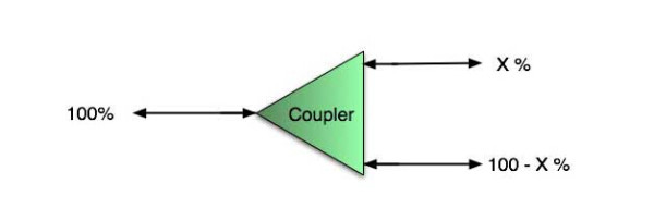
A fiber optic splitter is a device that splits the fiber optic light into several parts by a certain ratio. For example, when a beam of fiber optic light transmitted from a 1X4 equal ratio splitter, it will be divided into 4-fiber optic light by equal ratio that is each beam is 1/4 or 25% of the original source one. A Optical Splitter is different from WDM. WDM can divide the different wavelength fiber optic light into different channels. fiber optic splitter divide the light power and send it to different channels.

Most Splitters available in 900µm loose tube and 250µm bare fiber. 1×2 and 2×2 couplers come standard with a protective metal sleeve to cover the split. Higher output counts are built with a box to protect the splitting components.

Testing a coupler or splitter (both names are used for the same device) or other passive fiber optic devices like switches is little different from testing a patchcord or cable plant using the two industry standard tests, OFSTP-14 for double-ended loss (connectors on both ends) or FOTP-171 for single-ended testing.

First we should define what these passive devices are. An optical coupler is a passive device that can split or combine signals in optical fibers. They are named by the number of inputs and outputs, so a splitter with one input and 2 outputs is a 1×2 fiber splitter, and a PON splitter with one input and 32 outputs is 1×32 splitter. Some PON splitters have two inputs so it would be a 2X32. Here is a table of typical losses for splitters.

Splitter-Ratio

Important Note! Mode Conditioning can be very important to testing couplers. Some of the ways they are manufactured make them very sensitive to mode conditioning, especially multimode but even singlemode couplers. Singlemode couplers should always be tested with a small loop in the launch cable (tied down so it does not change and set the 0dB reference with the loop.) Multimode couplers should be mode conditioned by a mandrel wrap or similar to ensure consistency.

Let’s start with the simplest type. Shown below is a simple 1X2 splitter with one input and two outputs. Basically, in one direction it splits the signal into 2 parts to couple to two fibers. If the split is equal, each fiber will carry a signal that is 3dB less than the input (3dB being a factor of two) plus some excess loss in the coupler and perhaps the connectors on the splitter module. Going the other direction, signals in either fiber will be combined into the one fiber on the other side. The loss is this direction is a function of how the coupler is made. Some couplers are made by twisting two fibers together and fusing them in high heat, so the coupler is really a 2X2 coupler in which case the loss is the same (3dB plus excess loss) in either direction. Some splitters use optical integrated components, so they can be true splitters and the loss in each direction may different.
optical coupler

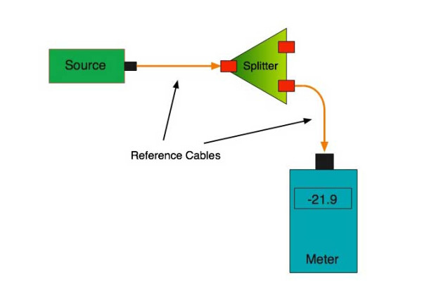
So for this simple 1X2 splitter, how do we test it? Simply follow the same directions for a double-ended loss test. Attach a launch reference cable to the test source of the proper wavelength (some splitters are wavelength dependent), calibrate the output of the launch cable with the meter to set the 0dB reference, attach to the source launch to the splitter, attach a receive launch cable to the output and the meter and measure loss. What you are measuring is the loss of the splitter due to the split ratio, excess loss from the manufacturing process used to make the splitter and the input and output connectors. So the loss you measure is the loss you can expect when you plug the splitter into a cable plant.

To test the loss to the second port, simply move the receive cable to the other port and read the loss from the meter. This same method works with typical PON splitters that are 1 input and 32 outputs. Set the source up on the input and use the meter and reference cable to test each output port in turn.

What about the other direction from all the output ports? (In PON terms, we call that upstream and the other way from the 1 to 32 ports direction downstream.) Simply reverse the direction of the test. If you are tesing a 1X2 splitter, there is just one other port to test, but with a 1X32, you have to move the source 32 times and record the results on the meter.
fiber-splitter

What about multiple input and outputs, for example a 2X2 coupler? You would need to test from one input port to the two outputs, then from the other input port to each of the two outputs. This involves a lot of data sometimes but it needs to be tested.

There are other tests that can be performed, including wavelength variations (test at several wavelengths), variations among outputs (compare outputs) and even crosstalk (put a signal on one output and look for signal on other outputs.)

Once installed, the splitter simply becomes one source of loss in the cable plant and is tested as part of that cable plant loss for insertion loss testing. Testing splitters with an OTDR is not the same in each direction.

Other Passive Devices

There are other passive devices that require testing, but the test methods are similar.

Fiber optic switches are devices that can switch an input to one of several outputs under electronic control. Test as you would the splitter as shown above. Switches may be designed for use in only one direction, so check the device specifications to ensure you test in the proper direction. Switches may also need testing for consistency after multiple switch cycles and crosstalk.

Attenuators are used to reduce signal levels at the receiver to prevent overloading the receiver. There is a page on using attenuators that you should read. If you need to test an attenuator alone, not part of a system, use the test for splitters above by using the attenuator to connect the launch and receive cables to see if the loss is as expected.

Wavelength-division multiplexers can be tricky to test because they require sources at a precise wavelenth and spectral width, but otherwise the test procedures are similar to other passive components.

Fiber optic couplers or splitters are available in a wide range of styles and sizes to split or combine light with minimal loss. All couplers are manufactured using a very simple proprietary process that produces reliable, low-cost devices. They are physically rugged and insensitive to operating temperatures. Couplers can be fabricated in custom fiber lengths and/or with terminations of any type.

DK Photonicswww.dkphotonics.com  specializes in designing and manufacturing of high quality optical passive components mainly for telecommunication, fiber sensor and fiber laser applications,such as PLC Splitter, WDM, FWDM, CWDM, DWDM, OADM,Optical Circulator, Isolator, PM Circulator, PM Isolator, Fused Coupler, Fused WDM, Collimator and Polarization Maintaining Components, Pump Combiner, High power isolator, Patch Cord and all kinds of connectors.

Optical Filters: Filter stacks transmit wide-angle incident light without shifting wavelength(2)

To avoid the problem of color change versus incidence angle in an optical system, thin-film-coated filter elements can be replaced by a filter consisting of a stack of different filter glasses.

JASON KECK

Wide-angle filter stack apps

There is a multitude of applications for this type of filter. In the field of digital imaging, colorimeters-which take wideband spectral energy readings-are used to profile and calibrate display devices, verifying that pixel color and intensity at the edge of a display matches the performance of pixels in the center of the display.

In astronomy, biomedical or fluorescence imaging, and mineralogy, hyperspectral imaging has many important applications. It is essential that the incident light undergo as little iridescence as possible. Also, when precision imaging instruments are expensively launched into orbit, the filters must be robust enough to withstand extreme environmental operating conditions.

In agriculture, the color of crops or food products reveals vital information. The use of Earth-observing satellites to measure the “vegetation index” of crops (a measurement of green hue) is nothing new, but the affordability of aerial drones has brought new possibilities. A drone can be programmed with GPS data to fly on a fixed pattern over a designated crop area and take wide-angle images at regular intervals, building up a picture of the vegetation index of crops. If the images used in such applications provide accurate spectral data that is as free as possible from iridescent distortion, it can give farmers precise control over fertilizer application rates and greatly improve efficiency and productivity. This is a considerable cost saving over low-resolution, narrowband satellite imagery and conventional aerial photography using manned aircraft.

Design hurdles

There are three complicating factors in the design of such filter stacks. The first is the limited choice in filter glass, limited not only by manufacturer availability but also by physics. Filter glass with an ideal edge cut-on or cut-off wavelength for an application is not always easy to find, or may be impossible to precisely manufacture. Where it is available, the designer is then limited by what the manufacturer can deliver in a reasonable time, as melts may be scheduled as infrequently as once every several years, depending on demand.

The second factor is that, while the perfect filter glass for a particular application may not exist, there are hundreds of other glass types from numerous vendors that can be combined to achieve a close approximation of the requirement.

The third complicating factor is that the design of ColorLock filters is a massively multidimensional, nonsmooth optimization challenge. Physical manufacturing requirements restrict the thickness of all combined individual layers to not exceed the overall thickness requirement of the resulting optical component, further putting restrictions on the selection of specific CWDM filter glass types.

Reynard streamlined this complex design process by developing in-house software into which all of the system requirements are fed. The software produces a manufacturable design for a filter in which the necessary materials are combined at the correct thickness in each layer. The design is then manufactured and validated for performance.

About DK Photonics

DK Photonics – www.dkphotonics.com  specializes in designing and manufacturing of high quality optical passive components such as 8CH CWDM Module,100GHz 8CH DWDM,200GHz DWDM,Mini-size CWDM,compact CWDM,Athermal AWG DWDM Module,100GHz AWG,Thermal AWG DWDM Module,1310/1490/1550nm FWDM, PLC Splitter, Optical Circulator,Optical Isolator,Fused Coupler,Mini Size Fused WDM.

Optical Filters: Filter stacks transmit wide-angle incident light without shifting wavelength(1)

To avoid the problem of color change versus incidence angle in an optical system, thin-film-coated filter elements can be replaced by a filter consisting of a stack of different filter glasses.

JASON KECK

Wide-angle imaging systems have to overcome numerous problems. Distortion of the shape of objects in the scene is the predominant issue, recognizable as the “fish-eye lens” look that is often corrected in software. However, lens distortion is not the only problem.

Iridescence, or the change in transmitted or reflected color of light viewed from different angles, is a phenomenon that can be found both in nature and in artificial light-detecting systems with precise color requirements, where it can cause many problems.

Wide-angle color-sensing applications commonly require that a CWDM wavelength must be detectable regardless of the incident angle. Iridescence through a thin-film-coated optical element can cause problems in this situation by distorting the spectral transmission of light coming from peripheral objects.

Maximizing light transmission in a thin-film WDM coating’s passband while blocking out-of-band light is a requirement for coated optical components such as dielectric filters; however, the wavelength’s transition commonly only remains steady within relatively narrow cone angles. Beyond angles of 5°, such filters are susceptible to iridescence, observable as a change of color, or “blueshift.” As the angle of light entering the filter increases, the light propagates through more of each thin-film stack layer, altering the apparent overall thickness of the optical-filter stack and affecting the performance of the original intended design. This can make such filters unsuitable for wide-angle imaging applications with bright illumination and where higher standards of consistency are required of the wavelength of all incident light.

One of the more convoluted wide-angle imaging solutions is the use of a cluster of cameras or a polycamera, pointing in various directions like the compound eye of an insect; the resulting multiple pictures are then assembled into one image in software. Although the light entering each camera thus fills only a narrow cone angle, the complexity and resultant high expense of such a system is obvious.

Engineers at Reynard have addressed this problem in a single optical device with a system in which two or more layers of filter glass are combined into a stacked configuration. These ColorLock filter stacks eliminate the wavelength shift as incident angle increases and are customized to meet specific system needs.

Software is used to determine the exact composition and thickness of the layers in these filters; the software determines a merit function that best estimates the filter requirements and allows filter stacks to be designed for band pass, short-wave pass, long-wave pass, or user-specified functions. Incident angles can be as high as 50° without any shift in the transmitted wavelength, while more traditional coated filters with the same conditions would see a significant shift toward shorter wavelengths.


About DK Photonics

DK Photonics – www.dkphotonics.com  specializes in designing and manufacturing of high quality optical passive components such as 8CH CWDM Module,100GHz 8CH DWDM,200GHz DWDM,Mini-size CWDM,compact CWDM,Athermal AWG DWDM Module,100GHz AWG,Thermal AWG DWDM Module,1310/1490/1550nm FWDM, PLC Splitter, Optical Circulator,Optical Isolator,Fused Coupler,Mini Size Fused WDM.

Ovum: Optical components market to grow 8% in 2014 from $6.8 bn in 2013

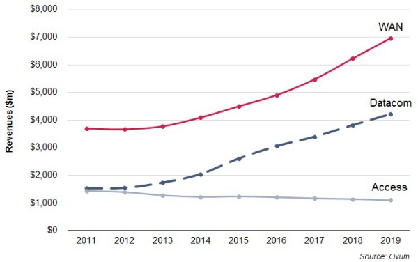
The global optical components (OC) market is expected to grow 8 percent in 2014 from $6.8 billion in 2013, said Ovum.

In 2013, the OC market increased 3 percent from 2012. Ovum said main growth drivers in 2013 were data communication sales driven by large data centers, 100G coherent demand, and unexpected growth in sales of transceivers for fiber-to-the-antenna applications for 4G build-outs.

“Demand for 100G metro–optimized transmission gear will begin shipments and ramp in 2015. Multiple component vendors introduced components and pluggable optics for 100GHz DWDM in anticipation. Opportunities are also emerging in the data center for high-speed interconnects,” said Daryl Inniss, practice leader for Telecoms Components at Ovum.

In the first quarter of 2014, the optical components market declined 1 percent sequentially and grew 7 percent compared to the year-ago period.  New lower telecom prices were one of the main reasons for the marginal growth in OC on quarter-on-quarter basis.

Ovm said demand for 100G components for coherent transmission in WAN, datacom transceivers at 10 and 40G, and fiber-to-the-antenna transceivers is expected to continue. Traffic continues to increase, and high-speed optics being used in new applications are helping to drive the market forward.

Global-optical-components-market-forecast

The WAN OC segment, which includes components in telecom carriers’ core and metro networks, the largest segment, will grow at a compound annual growth rate (CAGR) of 11 percent to $7 billion in 2019. Demand for 100G components and modules is a big driver for growth in WAN.  Ovum expects strong demand for pluggable coherent transceivers in 2015.

Datacom will be expanding at a 16 percent CAGR to reach $4.2 billion in 2019 — led by demand for 10 and 40G components in the early years and then 100G in the later years driven by the availability of server ports supporting data rates greater than 10G.

Access — including CATV, FTTx and transceivers for the fiber-to-the-antenna application — will decline at 2 percent CAGR to $1.1 billion in 2019. The decline will be driven by the FTTx application, where volumes are nearly constant through the forecast period but price declines are projected to pull down revenues.


DK Photonicswww.dkphotonics.com  specializes in designing and manufacturing of high quality optical passive components mainly for telecommunication, fiber sensor and fiber laser applications,such as PLC Splitter, WDM, FWDM, CWDM, DWDM, OADM,Optical Circulator, Isolator, PM Circulator, PM Isolator, Fused Coupler, Fused WDM, Collimator, Optical Switch and Polarization Maintaining Components, Pump Combiner, High power isolator, Patch Cord and all kinds of connectors.