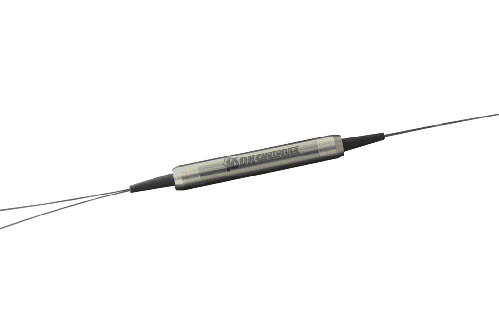
The 980/1030nm Polarization Maintaining Filter WDM multiplexes PM signals and maintains the output polarization with high extinction ratio using advanced micro-optic filter technology. All input and output fibers are polarization maintaining. It utilizes advanced filter technology to yield wide-band, low insertion loss, high polarization extinction, high return loss in a compact package. They are ideal for PM fiber amplifiers, fiber lasers and instrumentation applications.
|
PARAMETER
|
UNIT
|
T980/R1030
|
T1030/R980
|
|
|
Transmission Wavelength Range
|
nm
|
960~990
|
1020~1080
|
|
|
Reflect Wavelength Range
|
nm
|
1020~1080
|
960~990
|
|
|
Max. Insertion Loss@23℃
|
Transmission
|
dB
|
0.8
|
|
|
Reflect
|
dB
|
0.5
|
||
|
Min. Isolation@23℃
|
Transmission
|
dB
|
25
|
|
|
Reflect
|
dB
|
12
|
||
|
Min. Extinction Ratio@23℃
|
dB
|
20
|
||
|
Min. Channel Flatness
|
dB
|
0.3
|
||
|
Min. Return Loss
|
dB
|
50
|
||
|
Max. Power Handling(CW)
|
W
|
0.3, 0.7, 1, 2, 3, 5,10
|
||
|
Max. Tensile Load
|
N
|
5
|
||
|
Fiber Type
|
PM980-XP panda fiber
|
|||
|
Operating Temperature
|
℃
|
-5 to +70
|
||
|
Storage Temperature
|
℃
|
-40 to +85
|
||
|
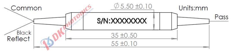
Package Dimensions
|
mm
|
Ø5.5 x L35
|
||
For high power applications, we will use heat sink package, contact DK Photonics for details. Please contact DK Photonics for confirmation.
| ① | ② | ③ | ④ | ⑤ |
| Wavelength | Power Handling | Pigtails Diameter | Fiber Length | Connector |
|
93:980nm pass/1030nm reflect
39:1030nm pass/980nm reflect
|
S:<0.3W
L:<0.7W
1:1W
2:2W
|
25:250μm bare fiber
90:900μm Loose Tube
XX: Others
|
05:0.5m
08:0.8m
10:1.0m
XX: Others
|
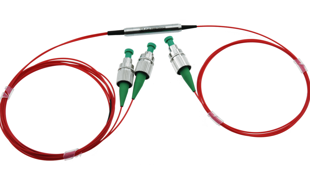
00: None
FP: FC/PC
FA: FC/APC
SA: SC/APC
LA: LC/APC
XX: Others
|
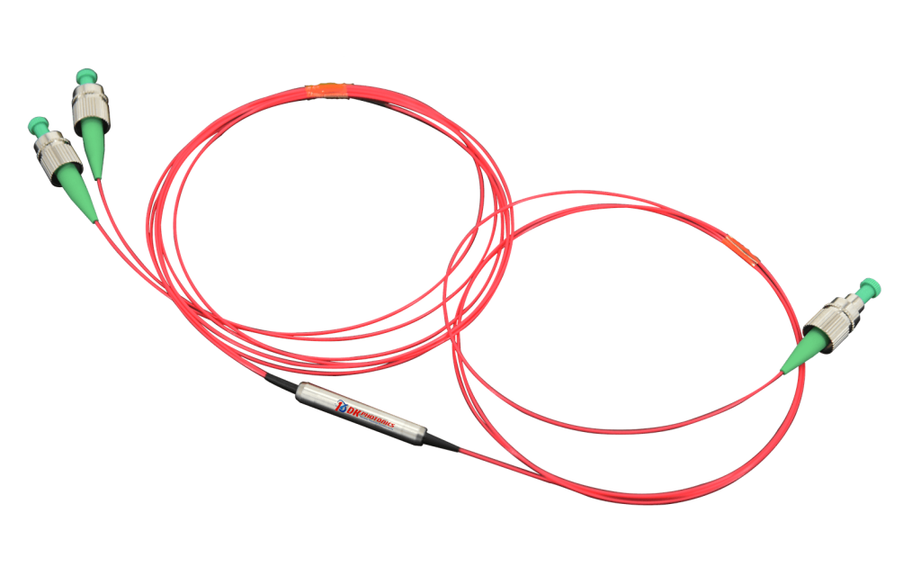
Description: 980/1030nm Polarization Maintaining Filter WDM – 1W, 1030 pass/980nm reflect, with 0.9mm OD loose tube, 1.0m fiber length, and FC/APC connectors at all ports.
If you need to customize other specifications, please provide detailed description for your requirement.
 DownloadDatasheet in PDF