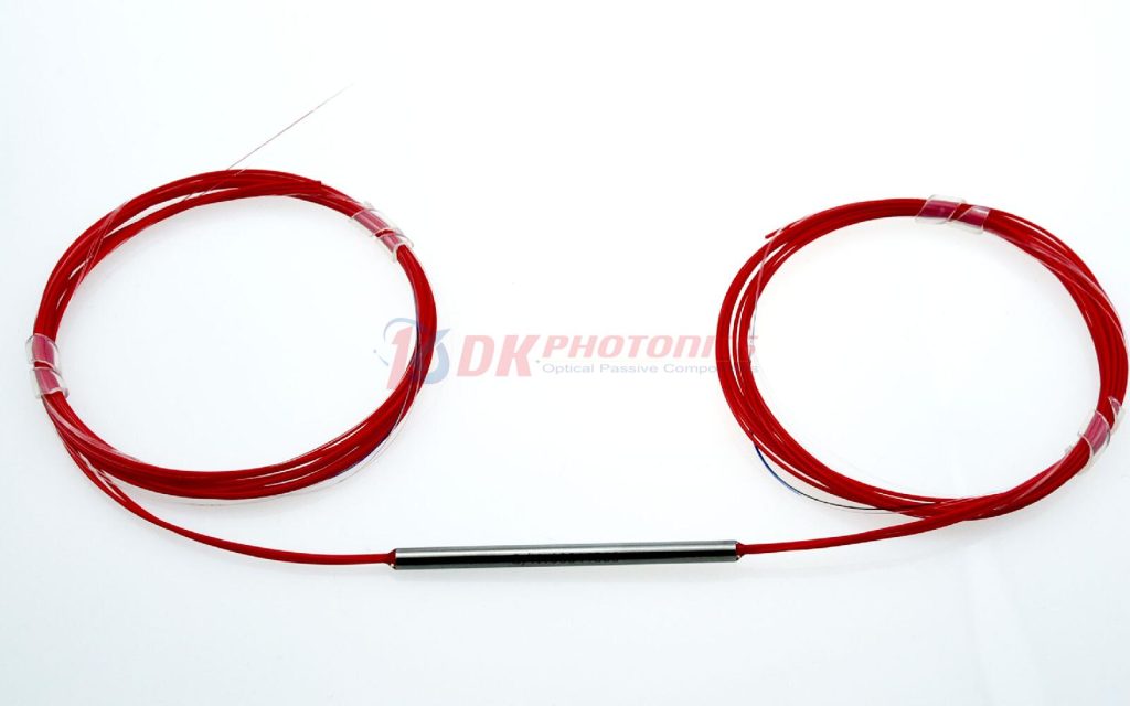

DK Photonics uses unique fusing technique and polarization maintaining fiber to build the 3×3 monolithic fused PM fiber standard splitter. The coupling ratio could be selected according to customer’s request. It features low excess loss, small size and high polarization extinction ratio. 3×3 monolithic fused PM fiber standard splitter is widely used for optical sensors and optical gyro.
DK Photonics uses unique fusing technique and polarization maintaining fiber to build the 1480nm 3×3 monolithic fused PM fiber standard splitter. The coupling ratio could be selected according to customer’s request. It features low excess loss, small size and high polarization extinction ratio. 3×3 monolithic fused PM fiber standard splitter is widely used for optical sensors and optical gyro.
If you do not see a standard PM Fused Coupler that meets your needs, we welcome the opportunity to review your desired specification and quote a custom PM fused Coupler. Requests for custom fiber pigtails, different wavelengths, tap Ratio and handling power of operation or other specific needs will be readily addressed.
| PARAMETER | UNIT | VALUES | ||
| Port Configuration | – | 3×3 | ||
| Splitting Ratio | % | 33/33/33 | ||
| Grade | – | P grade | A grade | |
| Central Wavelength | nm | 1480 | ||
| Bandwidth | nm | ±10 | ||
| Excess Loss | Typ. | dB | 0.6 | 0.8 |
|
Max. |
dB | 0.8 | 1.0 | |
| PER for Through Port | dB | ≥17 | ≥17 | |
| Splitting Ratio Tolerance | Max. | % | ±10 | ±13 |
| Directivity | dB | 50 | ||
| Max. Power Handling | W | 0.5, 2, 3, 5, | ||
| Max. Tensile Load | N | 5 | ||
| Fiber Type | – | PM1550 Panda fiber | ||
| Operating Temperature | ℃ | -5 ~ +70 | ||
| Storage Temperature | ℃ | -40 ~ +85 | ||
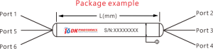
| Dimensions (Ф×L) | mm | Ф4.0×60(0.9mm tube), Ф3.0×54 (bare fiber) | ||
|
①
|
②
|
③
|
④
|
⑤
|
⑥
|
⑦
|
|
Grade
|
Port
|
Operating Wavelength
|
Power Handling
|
Pigtails Diameter
|
Fiber Length
|
Connector
|
|
P: P grade
A: A grade
|
303:3×3
|
14:1480nm
XX: Others
|
L:<0.5W
2:2W
5:5W
|
25:250μm bare fiber
90:900μm Loose tube
XX: Others
|
08:0.8m
10:1.0m
XX: Others
|
00: None
FP: FC/PC
FA: FC/APC
XX: Others
|
Description: 1480nm 3×3 Fused PM Fiber Splitter, slow axis working, P grade,0.5W, 33/33/33 coupling ratio, 1.0m PM1550 panda fiber with 0.9mm OD loose tube, and FC/APC connectors at all ports.
If you need to customize other specifications, please provide detailed description for your requirement.
1. Definition
Fused biconical fiber coupler (FBT coupler) is a kind of optical passive device which can couple the optical signal in the coupling region of special structure and redistribute it. In the early stage, it was mostly used to take out a certain power in the transmission trunk road for monitoring. With the rapid development of optical fiber technology, optical fiber coupler has been gradually developed1 × 2 / 2 × 2 / 1 × 3 or 3 × 3 and other coupling types, as well as a variety of different coupling ratio applications.
2. Characteristic
1). A beam of light can be divided into two or more beams according to a certain power ratio.
2). Wide working wavelength bandwidth, low additional loss, high stability and reliability.
3).Made by melting taper technology, it provides a variety of wavelength options in the wavelength range of 405 nm-2050 nm.
3.Description
1). Fused taper coupler
The fused taper coupler is composed of two parallel optical fibers The optical fibers are wound together in the high temperature environment, the optical fibers are gradually melted and stretched at the same time, so that the fiber cores of two optical fibers are gradually close to a certain distance. The area which these two optical fibers winding and fusion stretching is called Coupling Region, whose structure is shown in Figure 1:
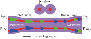
Figure 1. Schematic diagram of regional structure and optical coupling distribution of fused taper(Red is fiber core, Purple is cladding, Green and Blue are light).
The length L of the coupling region determines the coupling ratio of these two fibers. In the manufacturing process, the light wave is continuously input at the pin port, all the output power of each output port is monitored in real time. When the designed coupling ratio is reached, it would stop stretching. Such a coupler is essentially one optical fiber with two very close core and this process is called FBT(FBT,Fused Biconical Taper).
2). Theory
The intensity distribution of light passing through an optical fiber is basically a Gaussian distribution. That is, the strength is greatest at the center, the energy decreases as the center approaches the core/cladding interface. It is noteworthy that the tail energy of the Gaussian distribution extends slightly beyond the boundary between the fiber core and cladding, and the light wave of this tail energy is called evanescent wave. Figure 2 shows the energy distribution of light wave in the cross section of optical fiber. The vertical dotted line represents the fiber core / cladding boundary, and the red part is the evanescent wave energy.
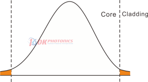
Figure 2 The energy distribution of light transmitted in optical fiber (The orange part represents the energy of evanescent wave.
During process of FBT, the cores of two parallel fibers are so close that evanescent waves can “leak” from one core to the other. The degree of energy exchange in the coupling region mainly depends on the spacing(d) between the cores and the length(l) of the coupling region. It can be found in Figure 1 that if the coupling length is long enough, the energy can be completely coupled from one fiber to another. If it is longer, the coupling process will continue to transfer energy back to the original fiber. By selecting the appropriate length, any given power transfer ratio can be realized. This is why we can make 50 / 50 or 10 / 90 coupling ratio by controlling the process.
3). Examples
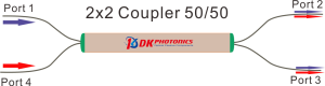
Figure 3. 2 × 2-port structure 50 / 50 tapered coupler.
As show in the Figure 3, it is fused taper coupler with 50/50 coupling ratio. Assuming that we input 1 mW and 1550 nm light to port 1 and port 4, how much optical power can we measure at output ports 2 and 3 respectively? Obviously, we will measure the power of 1 mW at each output port, and the light at each input port is divided into 50 / 50 equal parts.
Suppose we input 1 mW to port 1 and 2 mW to port 4. How much power can output ports 2 and 3 measure respectively? According to the previous conclusion, the input optical energy of each path is divided into two equal parts, so now we measure the power of 1.5 MW at each output port (port 1 provides 0.5 mW and port 4 provides 1 mW).
Suppose that the port 4 is now damaged (Generally, the three port devices are made into four ports first, and then the optical fiber of the four ports is broken and roughened to avoid the reflection echo generated by the smooth section), it becomes a 1 × 2 coupler. If we input 2 mW at port 1, it is easy to know that we will finally measure 1 mW at ports 2 and 3 respectively.
4). Reciprocity of tapered couplers
At a standard 2 × 2 coupler with 50 / 50 coupling ratio, if we flip the light direction of input and output, because of the symmetry of its structure, it is easy to understand that its forward and reverse transmission has the same properties. However, when using 1 × 2 coupler, people sometimes have doubts, because the obvious asymmetry of the device will give people an illusion that the working principle of its reverse transmission will be different from that of forward transmission.
Suppose that the port 4 is now damaged for the 2 × 2 coupler, if the light is input from the original two “output” ports 2 and 3, will the light come out of port 1 100%? Of course not. Light also wants to come out of the damaged port 4. Therefore, if we only input 1 mW from port 2, only 0.5 mW is output from port 1. Or we input 1 mW to port 2 and 2 mW to port 3, there would be 1.5 mW output from port 1 (port 2 provides 0.5 mW and port 3 provides 1 mW). This energy distribution is consistent with forward transmission. Therefore, the tapered coupler has reciprocity, and the forward and backward transmission has the same properties.
So, the 1 × 2 coupler is essentially a 2 × 2 coupler, just one the fiber was cut (To reduce reflection from the section).
5). Key parameters
Insertion Loss
The insertion loss is defined as the ratio of the input power to the output power at one of the output legs of the coupler (signal or tap). Insertion loss is always specified in decibels (dB). It is generally defined using the equation below:

where Pin and Pout are the input and output powers (in mW). For our 1×2 couplers, the insertion loss specification is provided for both signal and tap outputs; our specifications always list insertion loss for the signal output first. To define the insertion loss for a specific output (port 2 or port 3), the equation is rewritten as:


Insertion loss inherently includes both coupling (e.g., light transferred to the other output leg) and excess loss (e.g., light lost from the coupler) effects. The maximum allowed insertion loss for each output, signal and tap, are both specified. Because the insertion loss in each output is correlated to light coupled to the other output, no coupler will ever have the maximum insertion loss in both outputs simultaneously.
Calculating Insertion Loss using Power Expressed in dBm
Insertion loss can also be easily calculated with the power expressed in units of dBm. The equation below shows the relationship between power expressed in mW and dBm:
![]()
Then, the insertion loss in dB can be calculated as follows:
![]()
Excess Loss
Excess Loss refers to the overall energy transmission loss of the optical fiber coupler. It is defined in dB is determined by the ratio of the total input power to the total output power:

Pport1 is the input power at port 1 and Pport2+Pport3 is the total output power from Ports 2 and 3. All powers are expressed in mW.
Polarization Extinction Ratio (PER)
The polarization extinction ratio (PER) is a measure of how well a polarization-maintaining (PM) fiber or device can prevent cross coupling between the different polarization axes of the fiber. External stress on a fiber from sources such as heating, bending, or pulling can cause the PER to change.

Rotating Polarizer Method:
Rotating Polarizer Method is the most common method for measuring PER uses a low-coherence (unpolarized or circularly polarized) broadband light source and measures the extinction ratio with a linear polarizer and power meter.
The PER is measured using the following test measurement setup:
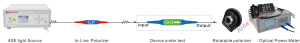
Figure 4. schematic diagram of measurement of polarization extinction ratio setup
Connect the components as shown above. Note that it is necessary to ensure that the panda eye of the PM fiber is perfectly aligned.
Adjust the rotatable polarizers sequentially until a minimum power value is measured by the power meter. Record the measured value as Pmin(dB).
Rotate the rotatable polarizers mount by 90°. Then record the measured value as Pmax(dB).
After Pmin and Pmax are measured, the extinction ratio can be calculated: PER(dB)= Pmax(dB) – Pmin(dB)
DK Photonics can provide a complete set of equipment/devices for the above measurement of extinction ratio setup, if you need it, please contact our sales: sales@dkphotonics.com.
Return Loss (RL)
The return loss refers to the fraction of input light that is lost in the internally terminated fiber end within the coupler housing when any port is used as the input. It can be calculated in units of dB using the following equation:

where P and Pb are the optical powers (in mW) in any port and the internally terminated fiber, respectively. This output is the result of back reflection at the junction of the legs of the coupler.
Directivity
Crosstalk between two output (port 2 and port 2) is referred to as directivity:

The light reflected from the coupler must be minimal so as not to interfere with the measurement signal. The sources of interference are kept as small as possible. This includes assembly and packaging of the connectors.
Usually, the return loss and directivity of the taper coupler are excellent. But if the coupler has a connector, the end face of the connector must be very clean, otherwise it will affect the return loss and directivity.
Coupling Ratio
Insertion loss (in dB) is the ratio of the input power to the output power from each leg of the coupler as a function of wavelength. It captures both the coupling ratio and the excess loss. The coupling ratio is calculated from the measured insertion loss. As show in the Figure 5, Coupling ratio (in %) is the ratio of the optical power from each output port (ports 2 and 3) to the sum of the total power of both output ports as a function of wavelength. Path A represents light traveling from port 1 to port 2 while Path B represents light traveling from port 1 to port 3.
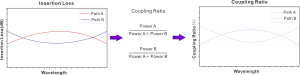
Figure 5. A graphical representation of the coupling ratio calculation.
Uniformity
The uniformity is also calculated from the measured insertion loss. Uniformity is the variation (in dB) of the insertion loss over the bandwidth. It is a measure of how evenly the insertion loss is distributed over the spectral range. Because different wavelengths of light in the optical fiber loss value is different, so the uniformity of optical fiber coupler is defined as: In the whole working wavelength range, the ratio of minimum output optical power Pmin Out and maximum output optical power Pmax Out, this indicates the stability of the output optical power when the input power changes within the working wavelength range. The smaller the uniformity value, the better (Note: Generally, the calculation result is negative, but the negative sign is often omitted in practice.).
 DownloadDatasheet in PDF