Order information
P/N: ISO-①-②-③-④-⑤-⑥-⑦
When you inquire, please provide the correct P/N number according to our ordering information, and attach the appropriate description would be better. If need any connector, we do not recommend choosing a 250μm bare fiber pigtail. For high power applications, we recommend direct splicing without connectors.
| ① |
② |
③ |
④ |
⑤ |
⑥ |
⑦ |
| wavelength |
Optical Power |
Power Type |
Fiber Type |
Pigtails Diameter |
Fiber Length |
Connector Type |
| 30:1030nm
40:1040nm
50:1050nm
XX: Other |
L:<0.5W
1:1W
3:3W
5:5W
10:10W |
P: Pulsed
C: Continuous Wave |
XX: fiber code |
25:250μm bare fiber
90:900μm Loose Fiber
XX: Others |
10:1.0m
XX: Other |
00: None
FP: FC/PC
FA: FC/APC
XX: Others |
Part Number Example: ISO-30-L-C-06X-90-10-FA
Description: TGG Based 1030nm Optical Isolator, 0.5W power handling, continuous wave power, 1060-XP fiber, with 0.9mm OD loose tube, 1.0m length fiber pigtails, FC/APC connectors at all ports.
Ordering Information for Custom Parts
If you need to customize other specifications, please provide detailed description for your requirement.
Optical Isolator Tutorial
Function
An optical isolator is a passive magneto-optic device that only allows light to travel in one direction. Isolators are used to protect a source from back reflections or signals that may occur after the isolator. Back reflections can damage a laser source or cause it to mode hop, amplitude modulate, or frequency shift. In high-power applications, back reflections can cause instabilities and power spikes.
An isolator’s function is based on the Faraday Effect. In 1842, Michael Faraday discovered that the plane of polarized light rotates while transmitting through glass (or other materials) that is exposed to a magnetic field. The direction of rotation is dependent on the direction of the magnetic field and not on the direction of light propagation; thus, the rotation is non-reciprocal. The amount of rotation β equals V x B x d, where V, B, and d are as defined below.
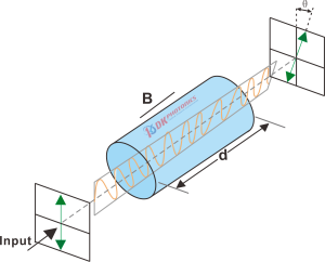
Figure 1.Schematic diagram of Faraday effect
Faraday Rotation
β = V x B x d
- V: the Verdet Constant, a property of the optical material, in radians/T • m.
- B: the magnetic flux density in teslas.
- d: the path length through the optical material in meters.
Single Mode optical Isolator
1.Definition
The single mode optical isolator is a passive magneto-optical device which uses the Faraday effect of magneto-optic crystal to isolate the reflected light and only allows the light to transmit in a single direction. The optical fiber isolators are used to protect light sources from adverse effects caused by back-reflection or signal.
2. Characteristic
1). Minimize Feedback into Optical Systems.
2). Low insertion loss and high-power handling capability.
3). Polarization independent structure.
3. Description
1). The principle of polarization independent isolator
Displacer type polarization independent isolator.
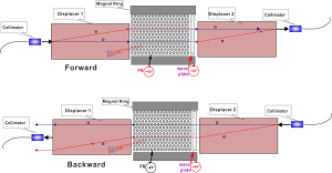
The structure and optical path of the Displacer optical isolator are shown in Figure 2, which consists of two collimators, two Displacer crystals, a half-wave plate, a Faraday rotator, and a magnetic ring. The forward light is incident on Displacer1 from collimator 1 and is divided into o light and e light for transmission. After passing through the half-wave plate and Faraday rotator, it rotates counterclockwise, and the conversion of o light and e light occurs, and is synthesized into a beam by Displacer 2 Coupling into the collimator 2; the reverse light is incident on the Displacer 2 from the collimator 2, and is divided into o light and e light for transmission. After passing through the Faraday rotator and half-wave plate, it rotates counterclockwise, and no o light and e light occur. The conversion of, after Displacer1, the two beams deviate from the collimator 1 and are isolated.
The disadvantage of the Displacer optical isolator is that in order to meet the isolation requirements, the two beams of light in the reverse optical path need to be shifted by a large distance, and the yttrium vanadate Displacer crystal with better birefringence , the ratio of the length to the offset can only be 10:1, which requires the Displacer crystal to be very large, resulting in a large device volume and high cost. But this kind of crystal usually has a higher Damage Threshold and is more suitable for using high power, such as 1030~1080nm TGG optical isolator.
Figure 2. structure schematic diagram of displacer type polarization independent isolator
2). The main parameters
a. IL (Insertion Loss)
Insertion loss refers to the additional loss caused by adding an optical isolator, and it is defined as the ratio of the optical power of the input and output ports of the optical passive components:
As shown in the formula above, Pout is the optical power of the output port, Pin is the optical power of the input port. The performance of isolator requires the insertion loss of forward light to be as small as possible. (Note: Generally, the calculation result is negative, but the negative sign is often omitted in practice.)
Figure 3. Schematic diagram of insertion loss test of the isolator
Take the red light as the example, the power for the input port Pin =100 mW, and the power of output port Pout=93 mW, so the IL of the channel 1 is:
IL = 10 × log (100/93)
= 10 × 0.032
= 0.32 dB
b. ISO (Isolation)
Isolation refers to the isolation ability of the optical isolator to reverse reflected light. It is defined as the decibel ratio of the power value of the reverse incident optical signal to the power value of the reverse output optical signal:
As shown in the formula above, PRin is the power of the inverted input, PRout is the power of the inverted output. The performance of the device requires the bigger isolation, the greater the isolation value of reflected light, the better.
Figure 4. Schematic diagram of isolation test of the isolator
Take the red light as the example, power of the inverted input PRin =100 mW, and thepower of the inverted output PRout=0.6 mW, so the IL of the channel 1 is:
ISO = 10 × log (100/0.6)
= 10 ×2.22
= 22.2 dB
 DownloadDatasheet in PDF