Filter WDM
1. Definition
FWDM(Filter Wavelength Division Multiplexin ) is the optical passive device, it can couple two or more different wavelengths of light into the same optical fiber transmission. It can also be a plurality of different wavelengths of light in the same optical fiber were separated into different optical fiber transmission.
2. Characteristic
1). To combine or separate two (usually two) or more beams of light of different wavelengths
2). Wide operating bandwidth, low insertion loss, high channel isolation, high stability and reliability.
3). Produced by dielectric film filter technology, it provides a variety of wavelength combinations in the wavelength range of 780 nm-20550 nm.
3. Description
1). Working principle of Filter WDM- Multilayer Dielectric Thin-film Filter
A thin-film resonant cavity filter (TFF) is a Fabry-Perot interferometer, or etalon, where the mirrors surrounding the cavity are realized by using multiple reflective dielectric thin-film layers.
This device acts as a bandpass filter, passing through a particular wavelength and reflecting all the other wavelengths. The wavelength that is passed through is determined by the cavity length.
To improve the reflection efficiency, the thin-film resonant multicavity filter (TFF) chip usually adopts multilayer film (generally 50-100 layers). By using the interference of multilayer dielectric film, one wavelength passes through and other wavelengths reflect.
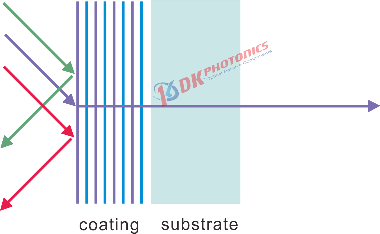
Figure 1. Working principle of thin-film WDM
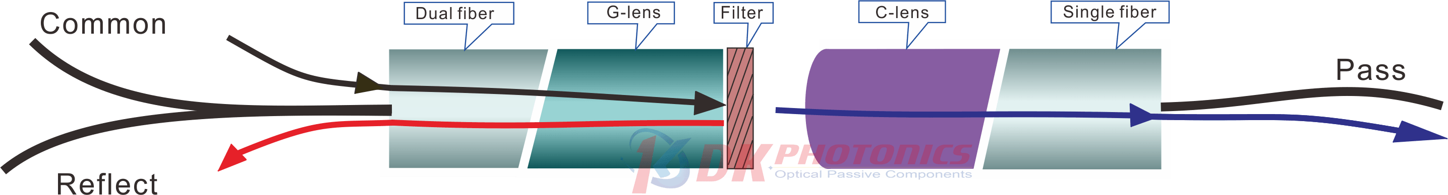
Figure 2. Schematic diagram of structure and wavelength selection of thin-film filter
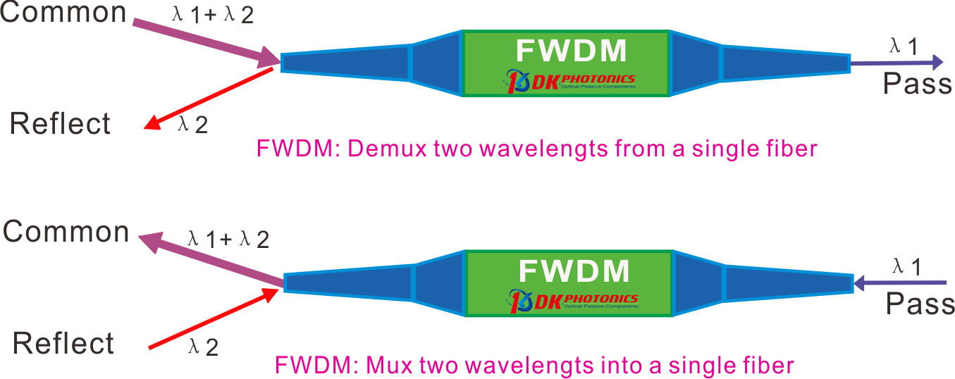
Figure 3. Schematic diagram of structure and wavelength selection of thin-film filter
When two different wavelength ranges of light are input from the common, WDM devices will allow one beam of light with the specific wavelength range to be transmitted and output from Pass port; The remaining light will be reflected and coupled to the Reflect port output, this is the process of wavelength division. According to the principle of reversible optical path. When different wavelengths of light input from Pass port and Reflect port, both lights will be coupled and output form the Common port by the WDM device, This is the process of optical wavelength multiplexing coupling.
Compared with fused WDM, the main feature of Filter WDM is that the wavelength range is more flexible. The user can specify any range of transmitted and reflected wavelengths.
2). key parameter
a. IL (Insertion Loss)
Insertion loss refers to the additional loss caused by passing WDM, which is defined as the ratio of the optical power of the input and output ports of the passive device:

As shown in the formula above, Pin is the power of the inverted input, Pout is the power of the inverted output. The performance of the device requires the insertion loss of forward incident light to be as small as possible
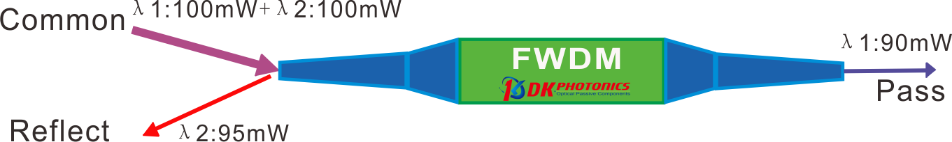
Figure 4. Schematic diagram of Insertion Loss test of WDM.
Taking the above figure 4 as an example, the blue light input is 100 mW, the output port is the Pass port; the red light input is 100 mW, and the output port is the Reflect port. It can be seen that the input optical power at the Pass pin = 100 mW, and the output optical power Pout = 90 mW, then the insertion loss IL of Pass port is:
IL= 10 × log (100/90)
= 10 × 0.046
= 0.46 dB
It can be known that the input optical power at the Reflect port Pin=100 mW, and the output optical power Pout= 95 mW, so the insertion loss IL of the Reflect port is:
IL= 10 × log (100/95)
= 10 × 0.022
= 0.22 dB
Note that the Insertion loss for the Reflect port will be better than the Pass port.
b. ISO (Isolation)
Isolation refers to the ability of one optical path of WDM to isolate the light in other optical paths. Each port of the WDM is designed to have low insertion loss (i.e., high transmission) at the desired wavelength while suppressing the signal at the specified wavelength of the other port, which minimizes cross talk between the ports. Therefore, isolation is specified as the insertion loss of these undesired wavelengths. High dB values of isolation are ideal for signal separation applications using a WDM.
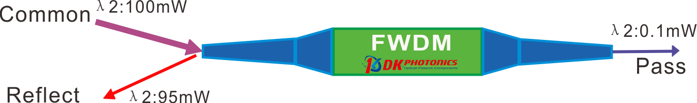
Figure 5. Optical path diagram of isolation test of the Pass port in WDM
Taking Figure 5 as an example, Pass port is the transmission channel port of blue light and Reflect port is the transmission channel port of red light. Theoretically, the red light input from Common port should be totally from Reflect port, However, the WDM can not completely isolate the red light output to the Pass port. To characterize the isolation ability of WDM to unexpected light, the concept of channel isolation is introduced.
Definition: the decibel of the ratio of the power value of the unexpected incident optical signal to the power value of the input optical signal:

As shown in the formula above, Pin is the input power, Pout is the output power of unexpected optical port. The WDM device requires that the higher the isolation value of the undesired light, the better the performance. At the same time, please note that the isolation indicators of the Pass port and the reflection port are inconsistent. Usually, the isolation on the Pass port will be higher.
Taking Figure 5 as an example, we know that the input optical power of red light Pin =100 mW, the output power for the unexpected light Pass port Pout=0.1 mW, and the ISO of the Pass port is:
IL= 10 × log (100/0.1)
= 10 × 3.00
= 30.0dB
As shown in the Figure 6, the input optical power of optical blue light Pin =100 mW, the output power for the unexpected light Reflect port Pout=2 mW, and the ISO of the Reflect port is:
IL= 10 × log (100/2)
= 10 × 1.699
= 16.99 dB
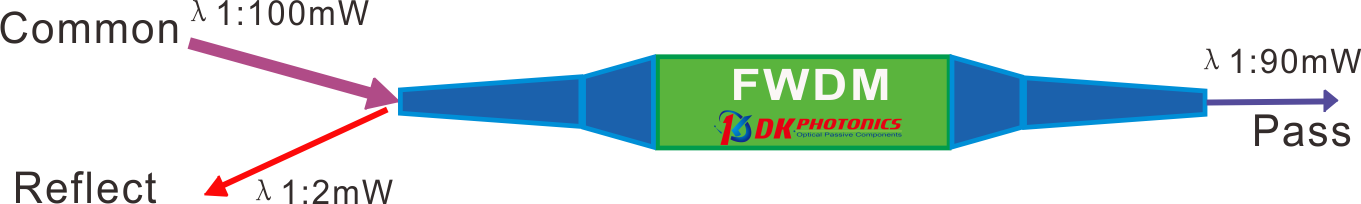
Figure 6. WDM Optical path diagram of isolation test of the Reflect port
 DownloadDatasheet in PDF