Understanding Pump and Signal Combiners

In the world of fiber optics, the efficiency and performance of optical systems rely heavily on components like pumps and signal combiners. These devices play a crucial role in combining multiple optical signals or pumps into a single output, simplifying optical setups and enhancing overall system performance.

What is a Pump and Signal Combiner?

A pump and signal combiner is a specialized optical component used in various fiber optic applications, particularly in fiber lasers and amplifiers. It’s designed to combine high-power pump lasers with low-power signal lasers into a single optical fiber, enabling efficient energy transfer and amplification.

How Does It Work?

  1. Combining Signals: The combiner merges pump signals, which provide the energy required for amplification, with weaker signal inputs, such as data signals, into a single optical path.
  2. Efficient Energy Transfer: By combining the signals, the combiner ensures that the pump energy efficiently transfers to the signal, enabling effective amplification without significant losses.
  3. Enhanced System Performance: With all signals merged into one fiber, the system becomes more compact, simpler, and easier to manage, leading to improved overall performance.

Applications

  1. Fiber Lasers: Pump and signal combiners are integral components in high-power fiber lasers, where they combine pump lasers with signal lasers to achieve efficient amplification and laser output.
  2. Fiber Amplifiers: In optical fiber amplifiers, these combiners play a crucial role in combining multiple pump sources with signal inputs for effective signal amplification.
  3. Telecommunications: They are also used in telecommunications networks for signal amplification and transmission over long distances.

Advantages

  1. Simplicity: By combining multiple signals into one fiber, the system design becomes simpler and more compact.
  2. Efficiency: Pump and signal combiners ensure efficient energy transfer between pump and signal sources, maximizing system performance.
  3. Cost-Effectiveness: They contribute to cost savings by reducing the need for additional optical components and simplifying system maintenance.

In conclusion, pump and signal combiners are essential components in fiber optic systems, enabling efficient energy transfer and amplification of optical signals. Their role in simplifying system design, enhancing performance, and reducing costs makes them indispensable in various applications across industries.

Optimizing Fiber Lasers with Pump and Signal Combiner

Introduction

Fiber lasers have revolutionized various industries with their exceptional efficiency and versatility. They are used in applications ranging from manufacturing and telecommunications to medical treatments and scientific research. One of the key aspects of maximizing the performance of fiber lasers is optimizing their design with pump and signal combiners. In this article, we will explore the significance of fiber laser optimization and delve into the role of pump and signal combiners in enhancing their capabilities.

Understanding Pump and Signal Combiners

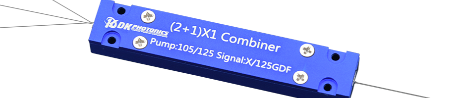
Pump and signal combiners are crucial components in fiber laser systems. The pump combiner is responsible for combining multiple pump laser sources into a single fiber, efficiently transferring energy to the gain medium. On the other hand, the signal combiner merges the output from the gain medium with the input signal, resulting in a high-power laser output.

These combiners play a pivotal role in the overall performance of fiber lasers, making them a focal point of optimization efforts.

Benefits of Optimizing Fiber Lasers

Optimizing fiber lasers offers several advantages that impact various applications:

Increased Efficiency and Power Output

By fine-tuning the pump and signal combiner, the overall efficiency of the fiber laser can be significantly improved. This optimization leads to a higher power output from the laser system, enabling more demanding applications.

Improved Beam Quality and Stability

A well-optimized fiber laser produces a high-quality output beam with excellent stability. This aspect is critical for applications that require precise and consistent laser beams.

Cost-effectiveness and Reduced Maintenance

Optimizing the fiber laser design can lead to a reduction in power consumption and lower maintenance requirements. These cost-saving benefits make fiber lasers more economically attractive for industrial applications.

Factors Affecting Fiber Laser Optimization

Several factors influence the optimization of fiber lasers:

Pump and Signal Combiner Designs

The design of pump and signal combiners plays a crucial role in the overall performance of fiber lasers. Different combiner configurations impact the efficiency and power handling of the laser.

Pump Wavelength and Power Considerations

Selecting the appropriate pump wavelength and power levels is essential for maximizing the absorption of pump light by the gain medium.

Signal Wavelength and Power Requirements

Optimizing the signal wavelength and power ensures compatibility with the gain medium and minimizes losses.

Fiber Length and Doping Concentration

The length of the fiber and the doping concentration affect the laser’s threshold and overall efficiency.

Temperature and Environmental Effects

Temperature fluctuations and environmental conditions can influence the performance and stability of fiber lasers.

Techniques for Optimizing Fiber Lasers

Various techniques are employed to optimize fiber lasers:

Mode Field Adaptation

Mode field adaptation techniques help in achieving high coupling efficiency between pump diodes and the fiber, enhancing overall performance.

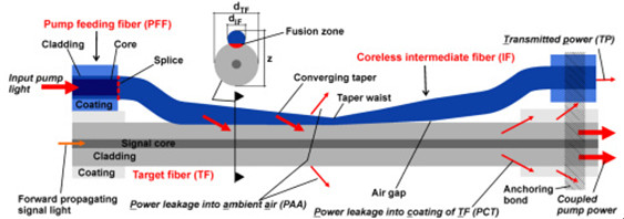
Tapered Fiber Designs

Tapered fiber designs allow for better control of nonlinear effects, enabling efficient power scaling.

Active Temperature Control

Implementing active temperature control ensures that the laser operates under the most favorable conditions.

Nonlinear Effects Management

Managing nonlinear effects is vital for achieving stable and consistent laser output.

Perplexity and Burstiness in Fiber Laser Optimization

Optimizing fiber lasers presents intricate challenges that require innovative solutions. The notion of perplexity comes into play when dealing with complex optimization scenarios. It refers to the measure of uncertainty and unpredictability, which must be managed to ensure a stable laser output.

Additionally, burstiness plays a significant role in fiber laser optimization. Burstiness refers to the sudden and transient spikes in laser output. Harnessing this burstiness effectively can lead to improved performance in specific applications.

The Role of Specificity and Context in Fiber Laser Optimization

Every fiber laser optimization effort must be specific to the intended application. The requirements for high-power industrial lasers differ from those of low-power medical lasers. Context, therefore, plays a pivotal role in designing the most suitable fiber laser system.

Engaging the Reader with Conversational Style

The world of fiber lasers is fascinating and filled with endless possibilities. These advanced laser systems are powering our modern world in ways we may not even realize. From cutting-edge manufacturing to groundbreaking medical treatments, fiber lasers are shaping the future.

So, what does this mean for you? Imagine being part of technological advancement, exploring the depths of laser technology, and unlocking new horizons in various industries. Fiber laser optimization not only enhances existing applications but also opens up doors to exciting uncharted territories.

Conclusion

In conclusion, optimizing fiber lasers with pump and signal combiners is a critical endeavor that unlocks their full potential. By addressing factors like combiner designs, wavelength considerations, fiber length, and temperature effects, we can achieve remarkable improvements in laser performance. The concept of perplexity adds depth to the optimization process, while burstiness offers unique advantages in specific applications. As we continue to explore the capabilities of fiber lasers, the future holds endless possibilities for innovation and discovery.

Pump and signal combiner for bi-directional pumping of all-fiber lasers and amplifiers(2)

2. Optical design and relevant ray paths of the fiber combiner

A schematic side view of the side-pump combiner consisting of a pump feeding fiber (PFF), a coreless intermediate fiber (IF) and a target fiber (TF) is shown in Fig. 1

high-power-isolator-1064nm

Fig. 1 Schematic side view of a side-pumped double-clad fiber including important ray paths.

. The diameter of the PFF core and the cladding was 105 and 125 µm, respectively. The NA of the pure silica PFF core used in the simulations was 0.15, 0.22 or 0.3 and, therefore, the refractive index of the PFF cladding was depressed in comparison to the refractive index of the PFF core. The cladding of the PFF was surrounded by a polymer coating only for mechanical protection of the fiber. Therefore, the PFF preserved the same waveguide properties after removal of the polymer coating. In the case of side-pumping without an IF, the higher refractive index of the core of the PFF would suppress the pump power transfer into the TF as long as the PFF is untapered. An increase of the NA of the pump light due to tapering of the PFF would result in an increase of the pump power transfer, though only for rays that exceed the NA of the PFF core. Thus, it is especially difficult to couple pump light rays with a low NA into the TF. Unfortunately, this type of PFF is typically used as high power delivery fiber of pump diodes. To overcome this problem, without removing the glass cladding of the PFF, a coreless IF was inserted in the fiber combiner setup. At first the ~30 cm long IF with a cladding diameter of 125 µm was fusion spliced to the PFF. The IF had a NA of 0.46 due to the refractive index difference (Δn) between fused coupler silica and the outermost polymer coating. After removing the polymer coating (e.g. with acetone) along a certain section of the IF (~15 mm), the IF was individually tapered, and afterwards the converging taper portion was laterally fused with the TF. The fusion level (FL) is defined as FL=(2z)/(dIF+dTF), where dIF and dTF are the cladding diameters of the IF and the TF at a certain taper position, respectively, and z represents the distance of the fused IF and TF, as depicted in Fig. 1. The FL was experimentally determined by measuring dIF, dTF and z at different positions along the converging taper portion with an optical microscope. With this measurement an averaged very low FL of 1.99 was determined, which was also used for the simulations. The overlap area between the TF and the IF is defined as the fusion zone. In contrast to the converging taper portion, the diverging taper portion of the IF was not fused to the TF, but placed under a small angle to the fiber axis of the TF, resulting in a small air gap between the IF and the TF. The employed TF was a DC fiber with a core diameter of 25 µm (NA 0.06) and a cladding diameter of 250 µm (NA 0.46). The cladding of the TF was also surrounded by a polymer coating, except along the coupling region of the combiner. The low index coating had to match the mechanical and additionally the optical properties of the DC fiber. An anchoring bond was used to fix the fiber bundle on each side on a copper substrate. Figure 1 shows the anchoring bond only on the right-hand side without the copper substrate. Additionally, the anchoring bond served as a pump light stripper for rays which do not satisfy the NA criterion of the TF.

Before proceeding with a more detailed investigation with the aid of simulations in the next section, we will qualitatively discuss some important ray paths of the fiber combiner. Pump light rays guided into the PFF and entering the tapered portion of the IF increase in NA as long as the rays propagate along the converging taper. As a rule of thumb, the pump light input NA increases by a factor of the taper ratio (TR), which is defined as the ratio of the original fiber diameter to the diameter of the taper waist. Pump light coupling into the TF occurs as soon the rays enter the fusion zone. The converging taper portion increases the probability for pump light transfer into the TF, since the number of ray-bounces along the lateral surface of the IF increases. Particularly, pump light rays with a low input NA couple more efficiently due to the converging taper.

Pump light rays remaining in the IF, and consequently not coupling into the TF, can occur as transmitted power (TP: transmittedpower, Fig. 1) or power leakage into the ambient air (PAA: power leakage into the ambient air, Fig. 1). As long as the condition for internal total reflection is satisfied, the pump light rays are detected as TP, otherwise the rays escape into the ambient air as PAA. The angle of total internal reflection for the uncoated IF is 43.6°, since Δn between fused silica and air is 0.45 at a wavelength of 976nm pump laser protector, which means the IF can guide light up to a theoretical NA of 1.05. Of course, the NA cannot exceed 1.0. Therefore, pump light rays with a theoretical NA in the range of more than 1.0 up to 1.05 would experience total reflection in the case of an existing fiber endface. Pump light rays which exceed the theoretical NA of 1.05 occur as PAA.

For almost loss-free pump light coupling into the TF it is necessary that the rays enter the TF before they exceed the cladding NA of the TF of 0.46. This desired coupling behavior can usually be achieved by adapting the taper parameters. However, pump light coupling for rays with an NA far above 0.46 cannot be completely suppressed. Unfortunately, this pump power leakage couple into the coating of the TF (PCT: power leakage into the coating of the target fiber) and can damage it.

In summary, the input pump combiner will be divided into the coupled pump power and the losses including PAA, PCT and TP (Fig. 1).