Introduction for CWDM MUX+DEMUX Module 8/16 Channels Dual Fiber with 1U 19 Rack Mount Box

Why do we choose CWDM MUX/DEMUX solution?

CWDM Mux/Demux is a flexible, low-cost solution that enables the expansion of existing fiber capacity. The CWDM Mux/Demux lets operators make full use of available fiber bandwidth in local loop and enterprise architectures. DK Photonics’ CWDM Mux/Demux is a universal device capable of combining up to 18 optical signals into a fiber pair or single fiber. It is designed to support a broad range of architectures, ranging from scalable point-to-point links to two fiber-protected rings. The important advantage of CWDM solution is the cost of the optics which is typically 1/3rd of the cost of the equivalent DWDM optics.

Description:

DK Photonics CWDM MUX+DEMUX Module 8/16 Channels (Dual Fiber) with 1U 19 Rack Mount Box utilize thin film coating technology and proprietary design of non-flux metal bonding micro optics packaging. Our 8CH CWDM Mux and Demux dual fiber 1U 19 Rack Mount Box support ITU-T G.694.2 wavelengths between 1270nm to 1610nm in 20nm increments. (Note: The ITU standard specifies the exact center of 8/16CH CWDM Mux and Demux dual fiber 1U 19 Rack Mount Box wavelength as 1531nm, 1591nm, 1611nm, etc. However, for clarity (and to comply with general industry conventions) the text in this data sheet refers to these wavelengths as 1530nm, 1590nm, 1610nm, etc.) 8/16 Channel CWDM Mux and Demux dual fiber 1U 19 Rack Mount Box are protocol and rate transparent allowing different services up to 10Gbps to be transported across the same fiber link. It allows for any protocol to be transported over the link, as long as it is at a specific wavelength (i.e. T1 over fiber at 1570nm transported alongside 10Gbps Ethernet at 1590nm). This allows for long-term future proofing of the networking infrastructure because the multiplexers simply refract light at any network speed, regardless of the protocol being deployed.

Our CWDM Mux/Demux can support up to 18 wavelengths between 1270nm to 1610nm in 20nm increments when com fiber is ITU-T G.694.2 , however if com fiber is ITU-T G.652, we recommend adopt 1270nm and 1290nm instead of 1390nm and 1509nm because of water peak loss.

DK Photonics’ provides a complete portfolio of CWDM Mux Demux and Optical Add Drop Multiplexer (OADM) units to suit all applications such as:- Gigabit & 10G Ethernet, SDH/SONET, ATM, ESCON, Fibre Channel, FTTx and CATV.

8/16 channel CWDM MUX+DEMUX in point to point application

Key Features

  • Up to 18 channels over 2 fibers
  • MUX and DEMUX combined 1U
  • Optical interfaces support all protocols from 30Mbps to 10Gbps, including OC-3/STM-1, OC-12/STM-4, OC-48/STM-16, OC-192/STM-64, Gigabit Ethernet SX, Gigabit Ethernet LX, Fast Ethernet, FDDI, ATM, ESCON, FICON, Fiber Channel, Coupling Link, 10G Ethernet
  • Distance up to 120km, based on used CWDM SFP+, CWDM XFP, CWDM X2, CWDM XENPAK, CWDM SFP, CWDM GBIC transceivers
  • Any configuration on demand
  • Your choice of adapter: SC, LC, E2000, MU etc
  • 19” 1U size or other according to customer requirements
  • For Central Office or Outside Plant
  • Compliant to ITU-T G.694.2 CWDM standard
  • ISO 9001 manufacturing facility
  • Fully transparent at all data rates and protocols from T1 to 40 Gbps
  • Completely passive, no power supply needed
  • Simple to install, requires no configuration or maintenance
  • Low-cost transceivers applicable, existing equipment can still be used

Applications

  • All Enterprises and Carrier with Fiber Optic Infrastructure
  • Transmit additional applications via existing lines
  • Connect buildings to CWDM campus ring
  • Connect Field offices to central office
  • Ideal solution for metro-core, metro-access and enterprises

DK Photonics’ 1RU Rack-mount chassis are made by best which can protect CWDM MUX/DEMUX inside well. These Low profile modular designs are widely used in computer centers, center office, IDC, OLT and FDC etc.

Introduction to CWDM Technology

CWDM (Coarse Wavelength Division Multiplexing) is a technology which multiplexes multiple optical signals on one fiber optic strand by making use of different wavelengths, or colors, of laser light to hold different signals. CWDM technology uses ITU standard 20nm spacing within the wavelengths, from 1270nm to 1610nm.

16CH CWDM Mux Module

CWDM In comparison with DWDM

Accordingly, they’ve got two important characteristics built into systems employing CWDM optical components which permit easier and for that reason also less expensive than in DWDM systems. CWDM is very easy in terms of network design, implementation, and operation. CWDM works together few parameters that want optimization from the user, while DWDM systems require complex calculations of balance of power per channel, which is further complicated when channels are added and removed or when it’s utilized in DWDM networks ring, particularly if systems incorporate optical amplifiers.


CWDM Function

CWDM modules perform two functions. First, they filter the lighting, ensuring only the desired wavelengths are used. Second, they multiplex or demultiplex multiple wavelengths, which are put on just one fiber link. The real difference is in the wavelengths, which might be used. In CWDM space, the 1310-band as well as the 1550-band are broken into smaller bands, each only 20-nm wide. Inside multiplex operation, the multiple wavelength bands are combined onto just one fiber. Within the demultiplex operation, the multiple wavelength bands are separated from one fiber.

Generally, a CWDM network takes two forms. A point-to-point system connects two locations, muxing and demuxing multiple signals for a passing fancy fiber. A loop or multi-point system connects multiple locations, typically using Add/Drop modules.


CWDM Modules Types

CWDM Modules utilize thin-film coating and micro optics package technology. CWDM modules consider two main configurations: CWDM Multiplexer/Demultiplexer (CWDM Demux) modules and CWDM Add/Drop Multiplexer (CWDM OADM) modules.

Mux products will include a few statistics symptoms in a only for having using a one-time fabric. Demux isolate all of the symptoms inside various terminate. Any value reaches an extra wavelength.

CWDM Mux/demux are created to multiplex multiple CWDM channels into One or two fibers. Within a hybrid configuration (mux/demux), multiple transmit and receive signals can be combined onto a single fiber. Each signal is assigned a different wavelength. At each and every end, transmit signals are muxed, while receive signals are demuxed. CWDM Mux/demux can be a flexible plug-and-play network solution, allowing carriers and enterprise companies to cheaply implement examine point or ring based WDM optical networks. CWDM Mux/demux is modular, scalable and it’s perfectly suited to transport PDH, SDH / SONET, ETHERNET services over WWDM, CWDM and DWDM in optical metro edge and access networks.

The most popular configuration of CWDM mux/demux is 2CH, 4CH, 5CH, 8CH, 9CH, 16CH and 18CH CWDM MUX/DEMUX. and also Compact CWDM module, 3 Single fiber or dual fiber connection for CWDM Mux/demux can also be found. These modules passively multiplex the optical signal outputs from 4 or higher electronics, send to them merely one optical fiber and then de-multiplex the signals into separate, distinct signals for input into technology along at the opposite end in the fiber optic link.

More information about CWDM: WDM Products

DWDM & CWDM Solutions

In today’s world of intensive communication needs and requirements, “fiber optic cabling” has become a very popular phrase.  In the field of telecommunications, data center connectivity and ,video transport, fiber optic cabling is highly desirable for today’s communication needs due to the enormous bandwidth availability, as well as reliability, minimal loss of data packets, low latency and increased security.  Since the physical fiber optic cabling is expensive to implement for each individual service, using a Wavelength Division Multiplexing (WDM) for expanding the capacity of the fiber to carry multiple client interfaces is a highly advisable.  WDM is a technology that combines several streams of data/storage/video or voice protocols on the same physical fiber-optic cable by using several wavelengths (frequencies) of light with each frequency carrying a different type of data. With the use of optical amplifiers and the development of the  OTN  (Optical Transport Network) layer equipped with FEC (Forward Error Corection), the distance of the fiber optical communication can reach thousands of Kilometers without the need for regeneration sites.


DWDM vs. CWDM

DWDM (Dense Wavelength Division Multiplexing) is a technology allowing high throughput capacity over longer distances commonly ranging between 44-88 channels/wavelengths and transferring data rates from 100Mbps up to 100Gbps per wavelength. Each wavelength can transparently carry wide range of services such as FE/1/10/40/100GBE, OTU2/OTU3/OTU4, 1/2/4/8/10/16GB FC,STM1/4/16/64, OC3/OC12/OC48/OC-192, HD/SD-SDI and CPRI.  The channel spacing of the DWDM solution is defined by the ITU.xxx (ask Omri) standard and can range from 25Ghz, 50GHz and 100GHz which is the most widely used today. Figure – 1 shows a DWDM spectral view of 88ch with 50GHz spacing.

50GHz spacing 88 DWDM channels/wavelengths

Figure -1: Spectral view of 50GHz spacing 88 DWDM channels/wavelengths

DWDM systems can provide up to 96 wavelengths (at 50GHz) of mixed service types, and can transport to distances up to 3000km by deploying amplifiers, as demonstrated in figure 2) and dispersion compensators thus increasing the fiber capacity by a factor of x100.  Due to its more precise and stabilized lasers, the DWDM technology tends to be more expensive at the sub-10G rates, but is a more appropriate solution and is dominating for 10G service rates and above providing large capacity data transport and connectivity over long distances at affordable costs. The DWDM solution today is often embedded with ROADM (Reconfigurable Optical Add Drop Multiplexer) which enables the building of flexible remotely managed infrastructure in which any wavelength can be added or dropped at any site. An example of DWDM equipment is well demonstrated by PL-1000, PL-1000GM, PL-1000GT, PL-1000RO, PL-2000 and PL-1000TN by DK Photonics Networks.

DWDM solution

Figure-2 Optical amplifier used in DWDM solution to overcome fiber attenuation and increase distance

CWDM (Coarse Wavelength Division Multiplexing) proves to be the initial entry point for many organizations due to its lower cost.  Each CWDM wavelength typically supports up to 2.5Gbps and can be expanded to 10Gbps support.  This transfer rate is sufficient to support GbE, Fast Ethernet or 1/2/4/8/10G FC, STM-1/STM-4/STM-16 / OC3/OC12/OC48, as well as other protocols.  The CWDM is limited to 16 wavelengths and is typically deployed at networks up to 80Km since optical amplifiers cannot be used due to the large spacing between channels. An example of this equipment is well demonstrated by PL-400, PL-1000E and PL-2000 by DK Photonics Networks.

It is important to note that the entire suite of DK Photonics’ equipment is designed to support both DWDM and CWDM technology by using standards based pluggable optical modules such as SFP, XFP and SFP+. The technology used is carefully calculated per project and according to customer requirements of distance, capacity, attenuation and future needs. DK Photonics also provides migration path from CWDM to DWDM enabling low entry cost and future expansion that can be viewed in the DWDM over CWDM technology page


WDM Installation

For designing and implementing a WDM network, there is a need to know some basic information regarding the infrastructure such as fiber type, attenuation of fiber, distance of fiber, network topology, service type, rate and connectivity. Based on this information, calculation of the optical link budget, OSNR (Optical Signal Noise Ratio) and dispersion can be performed in order to provide reliable, error free layer-1 optical solution.

DK Photonics’ WDM diversified equipment portfolio can provide either CWDM or DWDM solution for 4 wavelengths or 88 wavelengths ranging from few km to thousands of km and fit to the exact customer network needs. The network can be a point-to-point, linear add/Drop or ring Topology with passive Mux/DeMux or ROADM based infrastructure.

The WDM equipment serves as a demarcation point and is installed behind the Ethernet switch, router fiber channel SAN Fabric or SDH/SONET ADM coloring the fiber into different spectral wavelengths and multiplexing the rates fully isolated from each other over the same fiber to the remote site.  This allows transmission of multiple channels of different services and rates of data over the same fiber utilizing the fiber resources agnostically to the service type and rate.

The WDM technology can be applied to multiple applications such as connecting building service agnostic optical layer backbone,  data centers connectivity, Video broadcast, LTE fiber, cloud computing backbone, increasing existing fiber bandwidth and spectral efficiency.

Figure 3 shows the main traditional and emerging CWDM and DWDM technology applications which keep  growing along with the rise of the cloud computing and CSP (Content Service Providers) as well as Smart phones and video applications causing constant increase  to the WDM technology deployment and new capacities such as 100G.

Main CWDM and DWDM technology applications

Figure 3 – Main CWDM and DWDM technology applications

DK Photonics’ WDM products designed for easy and fast implementation take up minimal space and use least power, thus providing the highest integration level of CWDM and DWDM networks in the smallest 1U footprint, while providing high ROI. Additionally, the CWDM DWDM optical network is managed remotely with either DK Photonics’ Light Watch NMS/EMS or the imbedded web based management system as well as via any 3rd party SNMP tool.

Read more related articles :

Filter-based WDM          CWDM            Mini CWDM Module       DWDM

DWDM multiplexer and CWDM mux

As the DWDM mux/demux & CWDM mux/demux goods are playing an even more and more important role inside the data transmission field, today organic beef focus on the key options that come with DWDM mux and CWDM multiplexer first.

100G_32ch DWDM Module
16CH CWDM Mux Module

As everybody knows, DWDM which represents Dense Wavelength Division Multiplexing was created to multiplex DWDM channels into one or two fibers. This sort of products could make the optimum usage of your existing fiber optic infrastructure in an ideal way. It puts multiple signals together and sends them simultaneously along a fiber, simply with transmissions happening at different wavelengths, and also this turns an individual fiber to the virtual equal of a handful of fibers. It is really a good and also the most reasonable solution to date that will meet our increasing desires of large data transmissions. And also by using the impressive DWDM technique, it will transmit greater than 40 connections of numerous standards, data rates or protocols more than one common fiber optic link. For the DWDM products, the DWDM mux products combine several data signals into one for transporting on the single fiber as the DWDM demux (demulitplexers) separate the signals on the opposite end. Each signal reaches a different wavelength, they cooperate with each other perfectly.

The common configuration of DWDM mux is 4, 8, 16 and 32 channels. These DWDM modules passively multiplex the optical signal outputs from 4 or maybe more electronic devices, send on them an individual optical fiber and then de-multiplex the signals into separate, distinct signals for input into electronic devices in the opposite end with the fiber optic link.

The DWDM mux products always own these following features.

1.Low insertion loss and high isolation.

2.Simple to install, requires no configuration, and disassembles easily to clean.

3.Fully transparent at all data rates and protocols.

4.Completely passive, no power required, no cooling and so on.

And for the CWDM multiplexer, the core of CWDM Module application will be the passive mux/demux unit. The most popular configuration is 4 , 8 ,16 channels. Available in 19″ Rack Mount or LGX module package. Optional wide band port for existing 1310nm or 1550nm port is available to multiplex using these CWDM Channels. As well as our CWDM Transceiver series or perhaps the wavelength converter series, the bandwidth with the fiber can be employed in the economical way. The CWDM multiplexer is always be employed to improve your fiber capacity easily and quickly.

As the very best Chinese fiber optic products supplier, DK Photonics provides lots of this sort of products which are reliable and economical. If you may well not find it on our website (what we upload is the mux & demux inside a device), you can call us to customize it to suit your needs. For standalone multiplexers, it could increase dual fiber link capacity up to 18 channels and could be combined with a lot of the CWDM GBIC, SFP, XFP, X2, XINPAK, SFP modules. It’s also super easy to make use of and install, and also have some common features because the DWDM mux. Now it’s prepared to do the job, please do not hesitate to make contact with us. Thank you for visiting contact the DK Photonics representatives for more information if you need good quality and cost-effective DWDM mux and CWDM multiplexer products.

Application of Optical Add/Drop Multiplexer CWDM/DWDM Module

What’s the CWDM/DWDM Optical Add-drop Multiplexer?

The optical add-drop multiplexers (OADM) are used in wavelength-division multiplexing systems for multiplexing and routing different channels of light into or out of a single mode fiber. This is a type of optical node, which is generally used for the construction of optical telecommunications networks. An OADM may be considered to be a specific type of cross connect cabinet.

OADM ModuleOADM Module Application of OADM

A traditional OADM consists of three stages: an optical demultiplexer, and optical multiplexers, and between them a method of reconfiguring the paths between the optical demultiplexer, the optical multiplexer and a set of ports for adding and dropping signals. The optical demultiplexer separates wavelengths in an input fiber onto ports. The reconfiguration can be achieved by a fiber patch panel or by optical switches which direct the wavelengths to the optical multiplexer or to drop ports. The optical multiplexer multiplexes the wavelength channels that are to continue on from demultiplexer ports with those from the add ports, onto a single output fiber.

Principles of OADM technology

General OADM node can use four port model (Figure 1) to represent, includes three basic functions: Drop required wavelength signal, Add rumored signal to other wavelengths pass through unaffected. OADM specific network process is as follows: WDM signal coming from the line contains mangy wavelength signals into OADM’s “MainInput” side, according to business required, from many wavelength signals to selectively retrieved from the end (Drop) output desired wavelength signal, relative to the end from the Add the wavelength of the input signal to be transmitted. While the other has nothing to do with the local wavelength channels directly through the OADM, and rumored signals multiplexed together, the line output from the OADM (Main Output) Output.

OADM node technical classification

Optical drop multiplexer network technologies can be divided into two types, fixed optical drop multiplexer (Fixed OADM, FOADM) and reconfigurable optical drop multiplexer (Reconfigurable OADM, ROADM).

Fixed Optical Drop Multiplexer (FOADM)

FOADM to filter as the main component, and its function is fixed to join or retrieve certain light wavelengths. General common FOADM can be divided into three types, namely Thin Film Filter type (TFF type), Fiber Bragg Grating (FBG type) and integrated planar Arrayed Waveguide Gratings (AWG type).

* TFF FOADM using thin film between the filtering effect of the different refractive index.

* FBG FOADM use of fiber Bragg grating filtering effect, with two circulator can become FOADM.

* AWG FOADM gererally used in semiconductor fabrication processes, the integration of different refractive index material is formed on a flat substrate in a planar waveguide, when different wavelength light source is incident through the couping after the import side, due to take a different path length, while the different phase delay caused by different wavelengths and thus produce certain wavelengths in the export side to form a constructive or destructive interference, making waves in the export side, the different wavelengths will follow the design on a different channel to reach, and thus achieve FOADM function.

Reconfigurable Optical Add/Drop Multiplexer (ROADM)

ROADM can always be adjusted with the distribution network to add and drop wavelength, which reconstruct the network resource allocation, the flexibility to meet the requires of modern urban network, so a flexible ROADM features, plus optical switch substantial advantage, making the current fastest growing ROADM based optical switches based ROADM (switch based OADM). ROADM mainly be the optical switch, multiplexer and demultiplexer composed, Switch-based OADM, mainly divided into Wavelength independent switch array and wavelength selection switch.

OADM network applications

WDM ROADM optical fiber suitable for different network environments.

OADM in the metropolitan network development tendency

1. Arbitrary choice must be retrieved, adding wavelength, the wavelength can take advantage of the limited resources, the node can be retrieved with the need to do to join the adjustment of the signal wavelength, and has a remote control functions. This can provide dynamic reconfiguration of optical communications network capable ROADM will be connected to the backbone network critical devices. And FOADM is used for wavelength demand network access will be smaller parts to reduce costs. Furthermore, ROADM use to all kinds of Tunable Laser, unable Filter, or wavelength selective optical switches and other components.

2. Must be able to convert incompatible wavelength suitable for the backbone network will be transmitted wavelengths. Therefore, OADM be combined with wavelength conversioin Transponder or other functional components.

3. Must be able to compensate for the node to make acquisistion, adding such action energy loss. Therefore, OADM optical amplifiers must be combined with functional components.

4. Wavelength signals related specifications, such as: the signal to noise ratio (S/N), the energy balance between the signal wavelength, etc., are required to meet network requirements. Therefore must be combined OADM variable optical attenuators (VOA), dispersion compensation module (DCM) and other components.

Application of optical communication is still broad prospects

Once the Nortel global leader in fiber optic communications during the Internet bubble in 2000, the money in the acquisition of a large number of optical communications research and the production of small and medium enterprises, the industry has been criticized in the subsequent bankruptcy of Nortel. In fact, Nortel grasp of technology trends, the direction is right, unfortunately, Nortel too hasty, global demand for optical communication was not to such an extent.

But now the situation is very different compared with around 2000. The rapid development of mobile Internet and the widespread popularity of smart mobile terminal equipment, being a huge challenge to the global telecommunications network capacity, transmission speed. The era of “data flood peak to optical communication technology has always been known by the transmission bit of new development opportunities and a huge space. Optical communication technology not only did not fall behind, the contrary, the optical communication industry chain, from fiber optic cable system equipment, terminal equipment to optical devices, a critical period in the comprehensive technology upgrade.

The field of optical communication is a noteworthy event, the National Development and Reform Commission recently organizing the preparation of strategic emerging industries key products and services Guidance Catalogue, which in conjunction with the relevant departments, the optical communication technology and product responsibility and selected emerging industries of strategic focus products.

In fiber optics, including FTTx G.657 optical fiber, broadband long-distance high speed large capacity optical fiber transmission with G.656 optical fiber, photonic crystal fiber, rare earth doped fiber (including ytterbium doped fiber, erbium doped fiber and thulium doped fiber, etc.) the laser energy transmission fiber, and has some special properties of new optical fiber, plastic optical fiber, polymer optical fiber is fully finalists. The upgrade of the fiber optic technology, will bring the data transmission capacity, distance, quality leap.

In the field of fiber access equipment, passive optical network (PON), wavelength division multiplexer (WDM),OLT and ONU on the list. Optical transmission equipment, especially the line rate of 40 Gbit/s, 100Gbit/s large capacity (1.6Tb/s and abobe) DWDM equipment, reconfigurable optical bifurcation Multiplexer (ROADM) wavelength division multiplexing system ran cross-connect (OXC) equipment, large-capacity high-speed OTN optical transport network equipment as well as packetized enhanced OTN equipment, PTN packet transport network equipment also impressively. These products are “broadband China” works to promote a powerful weapon; both long-distance backbone network, metropolitan area network or access network even close to the user’s “last mile” of these products will come in handy.

The major products are classified as strategic emerging industries in the field of optical devices, high-speed optical components (active and passive). This is the core and foundation of the field of optical communication technology, device development, the improvement of integration, function enhancement can bring significantly reduce the cost of system equipment and provide a performance boost.

At the same time, the annual OFC / NFOEC (fiber-optic communications exhibition) will be held in late March in California. This event will showcase the latest technology and research progress of the global optical component modules, systems, networks and fiber optic products, represents a new trend of development of optical communication technology.

100G for ultra-high-speed network technology is the current OFC hot one. 2012 100G technology on a global scale backbone network level scale application of 100G optical network applications will rapidly expand with the 100G device further mature. In the same time, the industry has also increased efforts to develop the 100G optical modules, silicon photonics technology pluggable multi-source agreement 100G CFP MSA CPAK optical module has been available. Outside the backbone network, 100G MAN application is the current one of OFC discussion topic.

The rise of cloud computing brings data center construction boom, 100G technology in the data center is a popular data center for high-speed pluggable optical devices is also a hot topic. Experts believe that photonic technology has a key role to play in the large enterprise data centers, but this is only a start, the size of the new cloud computing data center such as a warehouse, with more than 100,000 servers carrying the computing and storage resources, the required network bandwidth than PB level. These data centers only optical communications technology in order to achieve VCSEL (vertical cavity surface emitting lasers) and multi-mode fiber has played an important role, and will continue to introduce new fiber optic communication technology.

Things You Should Know About Filter WDM

Wavelength-division multiplexing (WDM) is overtaking since the leading technology in point-to-point transmission links. One key method is a tunable optical filter. Important features of this type of filter include low insertion loss, narrow bandwidth, high sidelobe suppression, large dynamic range, fast tuning speed, a simple control mechanism, small size, and expense effectiveness. Filter WDM module will depend on Thin Film Filter (TFF) technology. The FWDM is extensively found in EDFA, Raman amplifiers, WDM networks and fiber optics instrumentation. The unit combines or separates light at different wavelengths in the wide wavelength range. Since FWDM series offer minimal insertion loss, low polarization dependence, high isolation and excellent environmental stability, perfect for very fast WDM network systems. It really is traditionally used in optical fiber systems:1310/1550nm, 1480/1550nm, 850/1310nm, 980/1550nm and 1310/1490/1550nm.

FWDM Main Features:

  •  Wide Operating Wavelength Range;
  •  Low Insertion Loss;
  •  Ultra Flat Wide Passband;
  •  High Channel Isolation;
  •  High Stability and reliability;
  •  Epoxy-free on Optical Path.
  •  FWDM Applications:
  •  Testing Instruments;
  •  FTTH Tri-Play System.

WDM is a method of combining multiple signals on lasers at various infared (IR) wavelengths for transmission along fiber optic media. Each laser is modulated by an impartial pair of signals. Wavelength-sensitive filters, the IR analog of visible-light color filters, are employed on the receiving end.

WDM is comparable to frequency-division multiplexing (FDM). But rather than going on at radio frequencies (RF), WDM is done inside the IR element of the electromagnetic (EM) spectrum. Each IR channel carries several RF signals combined by using FDM or time-division multiplexing (TDM). Each multiplexed IR channel is separated, or demultiplexed, in the original signals with the destination.

The usage of WDM can multiply the effective bandwidth of an fiber optic communications system with a large factor. However its cost should be compared to the choice of utilizing multiple fibers bundled in to a cable. A fiber optic repeater device referred to as erbium amplifier plans to make WDM a cost-effective long-term treatment for the bandwidth exhaustion problem.

DK Photonics offers a wide selection of WDM/CWDM/DWDM devices, like CWDM Mux/Demux, CWDM OADM, DWDM Mux/Demux, DWDM OADM, Filter WDM and so on. DK Photonics 1310/1490/1550 WDM devices based on thin-film filter technology are design to address the precise requirements from the FTTP market. Strong coating and passive device packaging capabilities feature these WDMs with excellent optical performance, good reliability and ultra-compact size.

Something you should know about CWDM DWDM and OADM

CWDM/DWDM Mux/Demux and OADM are all fit in with Passive. CWDM and DWDM technology produce an efficient strategy to share one set of fiber strands and hang together various communications interfaces, simply by using different wavelengths of light for each channel. Thus they could expand the proportions from the network without laying more fiber. And that i want to introduce the actual basical description of CWDM Mux/Demux, DWDM Mux/Demux and OADM.

As you know, Mux (Multiplexer) products combine several data signals into one for transporting over the single fiber. Demux (Demulitplexer) separates the signals at the opposite end. Each signal are at an alternative wavelength.

CWDM Mux/Demux

The Coarse Wavelength Division Multiplexing-CWDM Mux/Demux is often a flexible plug-and-play network solution, which helps insurers and enterprise companies to affordably implement denote point or ring based WDM optical networks. CWDM Mux/demux is perfectly suitable for transport PDH, SDH / SONET, ETHERNET services over WWDM, CWDM and DWDM in optical metro edge and access networks. CWDM tools are widely used in less precision optics and lower cost, un-cooled lasers with lower maintenance requirements. Weighed against DWDM and Conventional WDM, CWDM is a bit more affordable and much less power usage of laser devices. CWDM Multiplexer Modules can be found in 4, 8 and 16 channel configurations. These modules passively multiplex the optical signal outputs from 4 excessively electronic products, send on them somebody optical fiber and de-multiplex the signals into separate, distinct signals for input into gadgets along the opposite end for your fiber optic link.

DWDM Mux/Demux

The Dense Wavelength Division Multiplexing-DWDM Mux/Demux Modules are built to multiplex multiple DWDM channels into 1 or 2 fibers. Depending on type CWDM Mux/Demux unit, with optional expansion, can transmit and receive around 4, 8, 16 or 32 connections of standards, data rates or protocols more than one single fiber optic link without disturbing the other person. DWDM MUX/DEMUX modules provides best and low-cost bandwidth upgrade on your current fiber optic communication networks.

OADM

OADM(Optical Add-Drop Multiplexer) is often a device utilized in WDM systems for multiplexing and routing different channels of fiber into or out of a single mode fiber (SMF). OADM is made to optically add/drop one or multiple CWDM/DWDM channels into one or two fibers, provides capacity to add or drop an individual wavelength or multi-wavelengths from the fully multiplexed optical signal. This enables intermediate locations between remote sites gain access to the regular, point-to-point fiber segment linking them. Wavelengths not dropped pass-through the OADM and continue on in direction of the remote site. Additional selected wavelengths can be added or came by successive OADMS if required.

What is WDM? What Is the Difference Between DWDM and CWDM Optical Technologies?

What is WDM?

In the same optical fiber at the same time can let two or more than two wavelength signal transmit and receive information through different optical channel, called wavelength division multiplex, referred to as WDM. Wavelength division multiplexing includes frequency division multiplexing and wavelength division multiplexing. Optical frequency division multiplexing (FDM) technology and optical wavelength division multiplexing (WDM) technology has no obvious difference, because the light is part of the electromagnetic wave, frequency and wavelength of light have a single correspondence. Usually also can understand so, optical frequency division multiplexing mean subdivision of optical frequency, very dense optical channel. Wavelength division multiplexing means divided frequency of light, light channel far apart, even in the optical fiber with different window.

The general application of division multiplexing wavelength is respectively using a wavelength division multiplexer and demultiplexer arranged at both ends of the optical fiber, coupling and separation of different wavelength. The main four types of WDM are fused biconical taper type, dielectric film type, FBG type and planar waveguide grating type .The main characteristic is the insertion loss and isolation. Usually, the optical link using wavelength division multiplexing equipment, increase the amount of optical link loss is called WDM insertion loss. When the wavelength transmission through the same optical fiber, the D-value between the splitter input mixed power and the output end of the fiber power is called isolation.. The following are characteristics and advantages of optical wavelength division multiplexing technical:

(1) Make full use of low loss band fiber, increase the transmission capacity of optical fiber, the physical limit of an optical fiber for transmitting information doubled to several times. At present, we only use the low loss optical fiber spectrum (1310nm-1550nm) a few, WDM can fully utilize the huge bandwidth of single-mode fiber is about 25THz, the transmission bandwidth is sufficient.

(2) There are ability to transmit  two or more than two asynchronous signal in the same optical fiber ,there are compatible for digital and analog signals, has nothing to do with the data rate and modulation mode, the middle line can be removed or added channel.

(3) About the optical fiber system that has built, especially early laying optical cable that core number not much, as long as the original system power is margin, we can increase the capacity; realize the transmission of multiple one-way or two-way signals without making big changes to the original system, so it has strong flexibility.

(4) Due to the large number of reducing use amount of the fiber, it can greatly reduce the construction cost, because the fiber quantity is less, when a fault occurs, the recovery is also fast and convenient.

(5) Sharing of active optical devices, the cost of transmission of multiple signals or increase new business will reduce.

(6)The active devices in the system have been substantially reduced, which improves the reliability of the system. At present, because of the light multi carrier division multiplexing of optical transmitter, optical receiver equipment’s requirements higher, technology implementation has certain difficulty, also multiple core cable used in traditional broadcast television transmission business does not appear especially shortage, so the practical application of WDM is still not much. However, with the development of CATV integrated service development, the growing demand for network bandwidth, all kinds of selective service upgrade and network implementation economic cost considerations and so on, the characteristics and advantages of WDM in the CATV transmission system gradually emerged, showing broad application prospects, even influence the development pattern of CATV network.


What Is the Difference Between DWDM and CWDM Optical Technologies?

DWDM (dense wavelength division multiplexing) is undoubtedly the first choice technology in the field of fiber optic applications today, But the cause of high cost make many do not bounteous operators hesitating. Is there a lower cost for using the wavelength division multiplexing technology? In the face of this demand, CWDM (coarse wavelength division multiplexing) emerges as the times require.

CWDM, just as its name implies, is a dense wavelength division multiplexing next of kin, the difference between CWDM and DWDM mainly has two points: first, the CWDM carrier channel spacing is wider, therefore, light in a single fiber can reuse about 5 to 6 wavelengths, that is where the “dense” and “coarse” appellation come from; Two, CWDM modulation laser using uncooled laser, but DWDM is used in cooling laser. Cooling laser using temperature tuning, uncooled laser adopts electronic tuning. Because the range of temperature distribution is nonuniform in a very wide wavelength, so the temperature tuning is very difficult to realize, the cost is very high. CWDM avoids this problem, so it greatly reduces the cost; the whole CWDM system cost only 30% of DWDM.

CWDM provides a very high access bandwidth with a low cost, suitable for point to point, Ethernet, SONET rings and all kinds of popular network structure, especially suitable for short distance, high bandwidth, access point intensive, communication applications, such as network communication between the building or building. It is particularly worth mentioning is that CWDM with the use of PON (passive optical network).PON is a cheap, one-point to multi-point optical fiber communication mode, in combination with the CWDM, each individual wavelength channel can be used as virtual optical link of PON, Implementation of broadband data transmission between center node and multiple distributed nodes.

There are several companies are offering CWDM related products at present. However, CWDM is a product of cost and performance tradeoffs; inevitably there are some performance limitations. Industry experts point out, at present the CWDM have four following disadvantages: first, CWDM in a single fiber support multiplexing wavelength number is minor, leading to future expansion cost is high; second, multiplexing, multiplexing equipment cost should also be reduced, the device cannot be simply modified of DWDM corresponding equipment; third, CWDM does not apply to metropolitan area network, the distance between metropolitan area network nodes is short , the money that operators use in CWDM equipment expansion can be used to laying more fiber, and get better effect; fourth, CWDM has not yet formed standards.

What’s more, something about the WDM products.

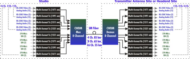
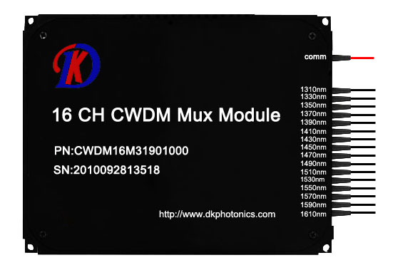
(1)CWDM Mux/Demux module

CWDM Mux and CWDM Demux are designed to multiplex multiple CWDM channels into one or two fibers. The core of CWDM Module application is the passive MUX DEMUX unit. The common configuration is 1×4, 1×8, 1×16 channels. Available in 19″ Rack Mount or LGX module package. Optional wide band port is available to multiplex with CWDM Channels wavelength.

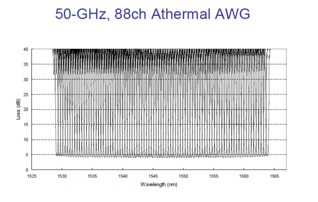
(2)DWDM Mux/Demux Modules

DWDM Mux and DWDM DeMux are designed to multiplex multiple DWDM channels into one or two fibers. The common configuration is 4, 8, 16 and 40 channels. These modules passively multiplex the optical signal outputs from 4 or more electronic devices, send them over a single optical fiber and then de-multiplex the signals into separate, distinct signals for input into electronic devices at the other end of the fiber optic link

(3)Optical Splitter– a important component in EPON network

Optical splitter in optical communication era is a component of EPON network construction, is a connection of OLT and ONU passive device.

Its function is to distribute the downlink data, and focus on the uplink data. Optical splitter has an upstream optical interface, a plurality of downlink optical interface. Optical signals from the upstream optical interface over was assigned to the downstream optical interface out all transmissions, optical signals from the downlink optical interface over being allocated to uplink optical interface out transmission only. The light intensity signal downlink optical interface of each can be same, can also be different.

Multiplexer and demultiplexer

In telecommunications and computer networks, multiplexing (muxing) is a method by which multiple analog message signals or digital data streams are combined into one signal over a shared medium. The goal is to share an expensive resource. For instance, in telecommunications, several telephone calls may be carried using one wire.

The multiplexed signal is transmitted over a communication channel, which may be an actual transmission medium. The multiplexing divides the capacity from the high-level communication channel into several low-level logical channels, one for every message signal or data stream to be transferred. A reverse process, known as demultiplexing, can extract the original channels around the receiver side. A tool that performs the multiplexing is known as multiplexer (Mux), along with a device that performs the reverse process is called a demultiplexer (Demux).

In electronics, a multiplexer is really a device that selects one of several analog or digital input signals and forwards the selected input right into a single line. A multiplexer of 2n inputs has n select lines, which are used to select which input line to send towards the output. Multiplexers are mainly used to increase the quantity of data that can be sent within the network within a specific amount of time and bandwidth. A multiplexer can also be called a data selector. An electronic multiplexer makes it possible for several signals to share one device or resource. Conversely, a demultiplexer is a device going for a single input signal deciding on one of several data-output-lines, which is connected to the single input. A multiplexer is often combined with a complementary demultiplexer on the receiving end. A digital multiplexer can be viewed as like a multiple-input, single-output switch, and a demultiplexer like a single-input, multiple-output switch. The schematic symbol for a multiplexer is an isosceles trapezoid with the longer parallel side containing the input pins and also the short parallel side containing the output pin. The schematic around the right shows a 2-to-1 multiplexer on the left and an equivalent switch on the right. The sel wire connects the specified input towards the output.

In the fiber optic area, a WDM system also utilizes a multiplexer in the transmitter to join the signals together, and a demultiplexer in the receiver to separate them apart. WDM systems are divided into different wavelength patterns, CWDM and DWDM. There are different Mux Demux for every of these.

The DWDM equipment, a DWDM multiplexer, actually contains one wavelength converting transponder for every wavelength signal it’ll carry. The wavelength converting transponders get the input optical signal, convert that signal into the electrical domain, and retransmit the signal utilizing a 1550 nm band laser. Additionally, it contains an optical multiplexer, which takes the different 1550 nm band signals and places them onto a single fiber. And also the DWDM demultiplexer breaks the multi-wavelength signal back into individual signals and outputs them on separate fibers for client-layer systems to detect. DWDM Mux and DWDM Demux are designed to multiplex DWDM channels into one or two fibers. The most popular configuration is 4, 8, 16 and 32 channels. The DWDM modules passively multiplex the optical signal outputs from 4 or more electronic devices, send on them a single optical fiber and then de-multiplex the signals into separate, distinct signals for input into electronics in the opposite end from the fiber optic link.

At the same time frame, there are CWDM multiplexer demultiplexer (CWDM Mux and CWDM Demux). They’re made to multiplex multiple CWDM channels into a couple of fibers. The core of CWDM Module application may be the passive Mux/Demux unit. The most popular configuration is 4, 8, and 16 channels. Optional wide band port for existing 1310nm or 1550nm port is available to multiplex with these CWDM Channels. Along with the CWDM transceiver series or the wavelength converter series, the bandwidth of the fiber may be used in a economical way.