3. Fabrication
The IF was fusion spliced to the DK Photonics with a filament splicing system (Vytran FFS-2000). A hydrogen-oxygen micro-flame was applied as heat source for tapering and lateral splicing of the IF. The working temperature for the tapering as well as the weak lateral splicing process of the IF was not measured but it can be assumed to be between the annealing and softening point of fused fiber coupler. The temperature adjusting was controlled by variation of the vertical distance between the fiber and the flame. Two precisely controlled motor stages were used to allow accurate alignment and tapering of the fiber(s). The heat source was placed at a fixed position in the center between the two motor stages. Each IF was individually tapered with a pulling speed of about 40 µm/s per motor stage and a fiber tension of about 10−2 N. After tapering, the IF was once twisted around the TF, which ensures that the converging taper portion remain in contact during lateral fusing. In case of a fiber combiner with several pump ports (see Section 5), the IFs were also individually tapered but simultaneously twisted around the TF. The final lateral fusion process along the converging taper portion was carried out at temperatures which allow sufficient softening of the tapered IF(s) and only slightly softening of the TF resulting in a weak fused component without any thermally induced damage of the core of the TF.
4. Simulations and experiments for a fiber combiner with a single pump port
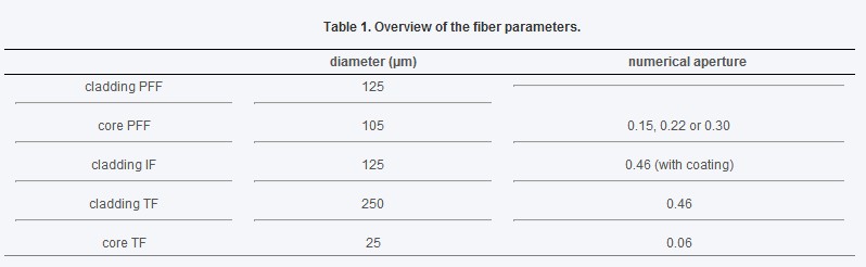
The ray tracing simulations were carried out with the commercially available software Zemax (Radiant Zemax, LLC) in the non-sequential mode. Detailed information about ray tracing in tapered cylindrical fibers can be found in Ref [16] and [17]. The ray tracing method is applicable due to the large cross sections of the employed fibers compared to the applied wavelength of 976 nm. The 3-dimensional simulation model of the fiber combiner was based on the setup depicted in Fig. 1 with the approximation of a parallel fiber arrangement of the IF and TF. For the PFF a fully filled condition was always assumed, meaning that all possible pump light rays, independent of the NA and the transversal position in the fiber core, carry equal power pump combiner. For the geometrical shape of the taper in the longitudinal direction, a simplified linear shape was assumed in the simulations, instead of the measured parabolic shape. As already mentioned, the FL was set to 1.99. Table 1 shows a summary of the fiber parameters used for simulations: