Fiber Optics: How Fused Fiber Optic Couplers Work in Modern Scenario

A fiber optic coupler is a gadget utilized as a part of optical fiber systems with at least one input fibers and one or a few output fibers. Light entering an input fiber can show up at least one outputs and its power distribution potentially relying upon the wavelength and polarization. Such couplers can be fabricated in various courses, for instance by thermally fusing fibers with the goal that their cores get into intimate contact. In the event that every single involved fiber are single-mode (supporting just a solitary mode for each polarization heading for a given wavelength), there are sure physical restrictions on the performance of the coupler. Specifically, it is unrealistic to consolidate at least two contributions of the same optical frequency into one single-polarization output without significant excess misfortunes. Be that as it may, such a limitation does not happen for various information wavelengths: there are couplers that can consolidate two contributions at different wavelengths into one output without exhibiting significant misfortunes. Wavelength-sensitive couplers are utilized as multiplexers in wavelength-division multiplexing (WDM) telecom systems to join a few information stations with various wavelengths, or to isolate channels.

Fiber optic couplers (fused couplers) are intended for control part and tapping media transmission hardware, CATV systems, and test gear. This sort of little parts are accessible independently or incorporated into modules for fiber security exchanging, MUX/DMUX, optical channel checking, and include/drop multiplexing applications.

Optical Fused Coupler

We utilize electronic couplers constantly, for example, a telephone coupler which gives you a chance to associate both a phone and a fax machine to a similar phone line. Fundamentally you can purchase these couplers from home depot or other electronic retailers.

Optical couplers have an indistinguishable usefulness from electronic couplers: they split the flag to numerous points (devices). Fiber optic couplers are required for tapping (monitoring the flag quality) or more complex telecommunication frameworks which require more than straightforward point-to-point connections, for example, ring architectures, bus architectures and star architectures.

Understanding the Use of Optical Fused Coupler, MUX & DEMUX WDM

In today’s high tech world, there is a desperate need for bandwidth.  The development of WDM (wavelength division multiplexing) technology has greatly helped us to expand the network capacity over a single fiber. A fiber optic coupler is a device used in fiber optic systems with input fibers (single or more) and output fibers (single or more). It is different from WDM devices.

The main benefits of Optical fused couplers are as follows:-

  • Combining: This Fiber Optic Couplers combine two signals and yield single output.
  • Splitting: The Splitters supply two outputs by using the single optical signal.

On the other hand, WDM multiplexer and demultiplexer divide the different wavelength fiber light into different channels. WDM is further divided into CWDM (coarse wavelength division multiplexing) and DWDM (dense wavelength division multiplexing). Generally, the WDM systems operate on 9µm single-mode fiber optical cables although it is not necessary.

If we specifically talk about the CWDM method, CWDM multiplexes multiple optical carrier signals on a single optical fiber. It uses different wavelengths/colors of laser light combined in a MUX in order to carry different signals. Mux/DeMux is one of the most important components of CWDM systems.

The LGX CWDM Mux and DeMux module comes with a 8 Channel (dual fiber) with 1U 19 Rack Mount Box that utilizes thin film coating technology and proprietary design of non-flux metal bonding micro optics packaging. It has been designed to provide optical networking support over a grid of CWDM optical wavelengths in high-speed Fibre Channel and Ethernet communication for metropolitan area networks (MAN).

The optical component is easy to operate with a reliable low-maintenance design. The MUX is passive and it does not use power supplies or electronics. It is capable of multiplexing and demultiplexing ITU-T G.694.2 wavelengths up to 8 channels in increments of 20nm from 1270 nm to 1610 nm. “ITU” specifies the exact center of 8CH CWDM Mux and Demux dual fiber 1U 19 Rack Mount Box wavelength such as 1531nm, 1591nm, 1611nm, etc.

The 8 Channel CWDM Mux and Demux dual fiber 1U 19 Rack Mount Box are protocol and rate transparent. They allow different services up to 10Gbps transported across the same fiber link. It works seamlessly with transceivers to optimize the link length, signal integrity, and overall network cost. It can be incorporated into a single rack-mount solution for a better design, power, and space efficiency.

As per the working principle, MUX and DEMUX can be used in various fields, such as communication systems, computer memories, telephone networks, etc. It is a cost saving method of connecting a multiplexer and a demultiplexer together over a single channel.

How to get the Optical Fused Couplers, Mux and DeMux WDM?

There are several leading companies in market that are considered masters at the designing and manufacturing of optical passive components for fiber laser, fiber sensor, and fiber optic telecommunication applications. One can contact these companies to avail high quality optical couplers, Mux and DeMux at affordable rates.

Contact DK Photonics today and get them.

Introduction of Fiber Optic Coupler with its Benefits & Classification

A fiber optic coupler is an indispensable part of the world of electrical devices. Without these no signals would be transmitted or converted from inputs to outputs. This is the reason these are so important thereby this article discussed about these, introduction, classification and benefits in detail.

Fiber Optic Coupler is an optical cog that is capable of connecting single or multiple fiber ends in order to permit the broadcast of light waves in manifold paths. This optical device is also capable of coalescing two or more inputs into a single output while dividing a single input into two or more outputs. In comparison to a connector or a splice, the signals may be even more attenuated by FOC i.e. Fiber Optic Couplers; this is due to the division of input signal amongst the output ports.

Types of Fiber Optic Coupler

Fiber Optic Couplers are broadly classified into two, the active or passive devices. For the operation of active fiber coupler an external power source is required, conversely no power is needed when it comes to operate the passive fiber optic couplers.

Fiber Optic Couplers can be of different types for instance X couplers, PM Fiber Couplers, combiners, stars, splitters and trees etc. Let’s discuss the function of each of the type of the Fiber Optic Couplers:

Combiners: This type of Fiber Optic Coupler combines two signals and yields single output.

Splitters: These supply multiple (two) outputs by using the single optical signal. The splitters can be categorized into T couplers and Y couplers, with the former having an irregular power distribution and latter with equal power allocation.

Tree Couplers: The Tree couplers execute both the functions of combiners as well as splitters in just one device. This categorization is typically based upon the number of inputs and outputs ports. These are either single input with a multi-output or multi-input with a single output.

PM Coupler: This stands for Polarization Maintaining Fiber Coupler. It is a device which either coalesces the luminosity signals from two PM fibers into a one PM fiber, or splits the light rays from the input PM fiber into multiple output PM fibers. Its applications include PM fiber interferometers, signal monitoring in its systems, and also power sharing in polarization sensitive systems etc.

Star Coupler: The role of star coupler is to distribute power from the inputs to the outputs.

Benefits of Fiber Optical Couplers

There are several benefits of using fiber optic couplers. Such as:

  • Low excess loss,
  • High reliability,
  • High stability,
  • Dual operating window,
  • Low polarization dependent loss,
  • High directivity and Stumpy insertion loss.

The listed benefits of Fiber Optical Couplers make them ideal for many applications for instance community antenna networks, optical communication systems and fiber-to-home technology etc.

2015-Fiber Optic Sensors Global Market Forecast

According to ElectroniCast, the combined use of Continuous Distributed and Point fiber optics sensors reached $2.28 Billion in 2014…

Aptos, CA (USA) – February 18, 2015  — ElectroniCast Consultants, a leading market/technology forecast consultancy, today announced the release of their market forecast and analysis of the global consumption selected Fiber Optic Point Sensors and Continuous Distributed Fiber Optics Sensor systems.

According to ElectroniCast, the consumption value of the combined use of Continuous Distributed and Point fiber optics sensors reached $2.28 Billion in 2014.

Continuous Distributed fiber optic sensor systems involve the optic fiber with the sensors embedded with the fiber.  ElectroniCast counts each Point fiber optic sensor as one unit; however, the volume of Distributed Continuous fiber optic sensors is based on a complete optical fiber line and associated other components, which are defined as a system.

“Since a distributed continuous optical fiber line (system) may have 100s of sensing elements in a continuous-line, it is important to note that ElectroniCast counts all of those sensing elements in a distributed continuous system as one (system) unit – only.  In the case of some applications, the price of the system may be several thousand dollars,” stated Stephen Montgomery, Director of the Fiber Optics Components group at ElectroniCast Consultants.

“POINT sensors are often used in Distributed fiber optic sensor systems (installed at multiple-points/ point-to-point); however, we count their use in the Point fiber optic sensor category and not in the continuous (non-stop) distributed sensor category,” Montgomery added.

DK Photonicswww.dkphotonics.com  specializes in designing and manufacturing of high quality optical passive components mainly for telecommunication, fiber sensor and fiber laser applications,such as 1064nm High Power Isolator,1064nm Components, PM Components, (2+1)x1 Pump Combiner,Pump Laser Protector,Mini-size CWDM,100GHz DWDM,Optical Circulator,PM Circulator,PM Isolator,Fused Coupler,Mini Size Fused WDM.

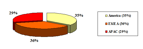
DATA FIGURE

According to ElectroniCast, The EMEA region held a slight lead in the worldwide consumption value of fiber optic sensors last year (2014)…

Fiber Optic Sensor Global Consumption Regional Market Forecast

($2.28 Billion in 2014)

Source: ElectroniCast Consultants

fiber optic coupler

Testing Fiber Optic Splitters Or Other Passive Devices

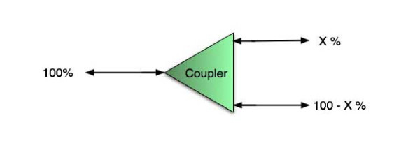
A fiber optic splitter is a device that splits the fiber optic light into several parts by a certain ratio. For example, when a beam of fiber optic light transmitted from a 1X4 equal ratio splitter, it will be divided into 4-fiber optic light by equal ratio that is each beam is 1/4 or 25% of the original source one. A Optical Splitter is different from WDM. WDM can divide the different wavelength fiber optic light into different channels. fiber optic splitter divide the light power and send it to different channels.

Most Splitters available in 900µm loose tube and 250µm bare fiber. 1×2 and 2×2 couplers come standard with a protective metal sleeve to cover the split. Higher output counts are built with a box to protect the splitting components.

Testing a coupler or splitter (both names are used for the same device) or other passive fiber optic devices like switches is little different from testing a patchcord or cable plant using the two industry standard tests, OFSTP-14 for double-ended loss (connectors on both ends) or FOTP-171 for single-ended testing.

First we should define what these passive devices are. An optical coupler is a passive device that can split or combine signals in optical fibers. They are named by the number of inputs and outputs, so a splitter with one input and 2 outputs is a 1×2 fiber splitter, and a PON splitter with one input and 32 outputs is 1×32 splitter. Some PON splitters have two inputs so it would be a 2X32. Here is a table of typical losses for splitters.

Splitter-Ratio

Important Note! Mode Conditioning can be very important to testing couplers. Some of the ways they are manufactured make them very sensitive to mode conditioning, especially multimode but even singlemode couplers. Singlemode couplers should always be tested with a small loop in the launch cable (tied down so it does not change and set the 0dB reference with the loop.) Multimode couplers should be mode conditioned by a mandrel wrap or similar to ensure consistency.

Let’s start with the simplest type. Shown below is a simple 1X2 splitter with one input and two outputs. Basically, in one direction it splits the signal into 2 parts to couple to two fibers. If the split is equal, each fiber will carry a signal that is 3dB less than the input (3dB being a factor of two) plus some excess loss in the coupler and perhaps the connectors on the splitter module. Going the other direction, signals in either fiber will be combined into the one fiber on the other side. The loss is this direction is a function of how the coupler is made. Some couplers are made by twisting two fibers together and fusing them in high heat, so the coupler is really a 2X2 coupler in which case the loss is the same (3dB plus excess loss) in either direction. Some splitters use optical integrated components, so they can be true splitters and the loss in each direction may different.
optical coupler

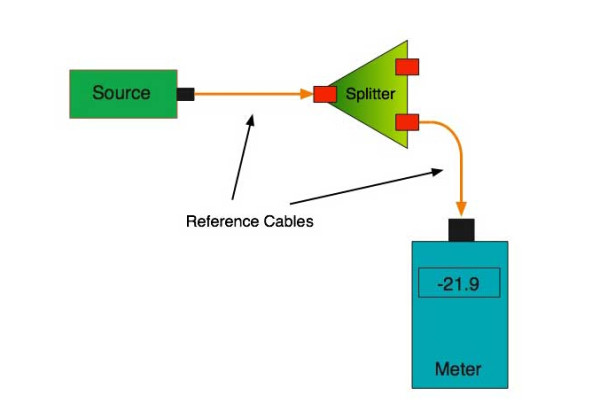
So for this simple 1X2 splitter, how do we test it? Simply follow the same directions for a double-ended loss test. Attach a launch reference cable to the test source of the proper wavelength (some splitters are wavelength dependent), calibrate the output of the launch cable with the meter to set the 0dB reference, attach to the source launch to the splitter, attach a receive launch cable to the output and the meter and measure loss. What you are measuring is the loss of the splitter due to the split ratio, excess loss from the manufacturing process used to make the splitter and the input and output connectors. So the loss you measure is the loss you can expect when you plug the splitter into a cable plant.

To test the loss to the second port, simply move the receive cable to the other port and read the loss from the meter. This same method works with typical PON splitters that are 1 input and 32 outputs. Set the source up on the input and use the meter and reference cable to test each output port in turn.

What about the other direction from all the output ports? (In PON terms, we call that upstream and the other way from the 1 to 32 ports direction downstream.) Simply reverse the direction of the test. If you are tesing a 1X2 splitter, there is just one other port to test, but with a 1X32, you have to move the source 32 times and record the results on the meter.
fiber-splitter

What about multiple input and outputs, for example a 2X2 coupler? You would need to test from one input port to the two outputs, then from the other input port to each of the two outputs. This involves a lot of data sometimes but it needs to be tested.

There are other tests that can be performed, including wavelength variations (test at several wavelengths), variations among outputs (compare outputs) and even crosstalk (put a signal on one output and look for signal on other outputs.)

Once installed, the splitter simply becomes one source of loss in the cable plant and is tested as part of that cable plant loss for insertion loss testing. Testing splitters with an OTDR is not the same in each direction.

Other Passive Devices

There are other passive devices that require testing, but the test methods are similar.

Fiber optic switches are devices that can switch an input to one of several outputs under electronic control. Test as you would the splitter as shown above. Switches may be designed for use in only one direction, so check the device specifications to ensure you test in the proper direction. Switches may also need testing for consistency after multiple switch cycles and crosstalk.

Attenuators are used to reduce signal levels at the receiver to prevent overloading the receiver. There is a page on using attenuators that you should read. If you need to test an attenuator alone, not part of a system, use the test for splitters above by using the attenuator to connect the launch and receive cables to see if the loss is as expected.

Wavelength-division multiplexers can be tricky to test because they require sources at a precise wavelenth and spectral width, but otherwise the test procedures are similar to other passive components.

Fiber optic couplers or splitters are available in a wide range of styles and sizes to split or combine light with minimal loss. All couplers are manufactured using a very simple proprietary process that produces reliable, low-cost devices. They are physically rugged and insensitive to operating temperatures. Couplers can be fabricated in custom fiber lengths and/or with terminations of any type.

DK Photonicswww.dkphotonics.com  specializes in designing and manufacturing of high quality optical passive components mainly for telecommunication, fiber sensor and fiber laser applications,such as PLC Splitter, WDM, FWDM, CWDM, DWDM, OADM,Optical Circulator, Isolator, PM Circulator, PM Isolator, Fused Coupler, Fused WDM, Collimator and Polarization Maintaining Components, Pump Combiner, High power isolator, Patch Cord and all kinds of connectors.

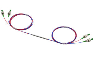
Industrial Fiber Laser Introduction and Global Market Forecast –DK Photonics

The Global Industrial Fiber Laser market to grow at a CAGR of 21.4% over the period 2013-2018

Fiber lasers contain the active gain medium, which is an optical fiber integrated with rare earth elements such as erbium and ytterbium. Unlike conventional gas lasers, a fiber laser uses part of the fiber as the resonating cavity, where the laser action takes place to generate laser beams , Fiber lasers are preferred over other lasers such as CO2 lasers and excimer lasers, primarily because they are more reliable, efficient, robust, and portable, and easier to operate than other lasers.

Fiber lasers used for industrial applications such as cutting, welding, marking, and engraving in the Manufacturing, Semiconductor, and Automotive industries are referred to as industrial fiber lasers. Moreover, due to their superior performance, compact size, high output power, low cost of ownership, durability, and eco-friendly attributes, industrial fiber lasers are being adopted at a significant rate. They also eliminate the mechanical adjustments and high maintenance costs that are necessary with other lasers.

Increased R&D spending by vendors to gain a competitive advantage over other players in the market is one key trend in this market. Vendors are increasingly investing in their R&D division to provide better functionality and to meet the unsatisfied requirements of consumers. R&D investments have enabled vendors to capture a significant market share and gain a competitive edge over other vendors in the Global Industrial Fiber Laser market.

According to the report, one major driver of the market is the increased adoption of fiber lasers because of their superior attributes. These lasers used for industrial applications are gaining more significance because they exhibit excellent light properties.

Further, the report states that one of the key challenges that the market faces is the uncertainty regarding the lifespan of fiber lasers. Despite their existence in the industry for more than 10 years, the lifespan fiber lasers are not definite.


DK Photonics – www.dkphotonics.com  specializes in designing and manufacturing of high quality optical passive components mainly for fiber laser applications such as 1064nm high power isolator, Cladding Power Stripper, Multimode High Power Isolator, pump combiner,1064nm Band-pass Filter,(6+1)X1 Pump and Signal Combiner, PM Circulator, PM Isolator, optical Coupler. More information, please contact us.

Differences Between FBT Coupler and PLC splitters

Optical networks require signal being splitted somewhere in design to serve for multiple customers. Splitter technology has made a huge step forward in the past few years by introducing PLC (Planar Lightwave Circuit) splitter. It has proven itself as a higher reliable type of device compared to the traditional FBT (Fused Biconical Taper) splitter. While being similar in size and outer appearance, both types of splitters provide data and video access for business and private customers. However, internally the technologies behind these types vary, thus giving  service providers a possibility to choose a more appropriate solution.

FBT splitter is made out of materials that are easily available, for example steel, fiber, hot dorm and others. All of these materials are low-price, which determines the low cost of the device itself. The technology of the device manufacturing is relatively simple, which has the impact on its price as well. In scenario where multiple splits are needed, the size of the device may become an issue. It is important to keep in mind that splitters are being deployed in the fields either in cabinets or in strand mountings, so the size of device plays a critical role. FBT splitters only support three wavelengths (850/1310/1550 nm) which makes these devices unable to operate on other wavelengths. Inability of adjusting wavelengths makes FBT splitters less customizable for different purposes. Moreover, the devices are to a high extent temperature sensitive, providing a stable working range of -5 to 75 C. In certain areas, such as Scandinavian countries this temperature restrictions may be crucial. The signal processed by FBT splitters cannot be splitted evenly due to lack of management of the signals

PLC splitter manufacturing technology is more complex. It uses semiconductor technology (lithography, etching, developer technology) production, hence it is more difficult to manufacture. Therefore, the price of the device is higher. However, there is a number of advantages the device possesses. The size of the device is compact, compared to FBT splitters, making it suitable for density applications. PLC splitter operates at wider temperature range (-40 to 85 C), allowing its deploying in the areas of extreme climate. The split ratio goes up to 64, providing a high reliability. Furthermore, the signal can be split equally due to technology implemented. A range of wavelengths (1260 – 1650 nm) is provided, so the wavelengths are adjustable. Critical points of the device that might fail are input and output, so the general risk of failure is low.

Differences Between FBT and PLC splitters

 Table 1. FBT and PLC splitter feature comparison

DK Photonicswww.dkphotonics.com  specializes in designing and manufacturing of high quality optical passive components mainly for telecommunication, fiber sensor and fiber laser applications,such as PLC Splitter, WDM, FWDM, CWDM, DWDM, OADM,Optical Circulator, Isolator, PM Circulator, PM Isolator, Fused Coupler, Fused WDM, Collimator, Optical Switch and Polarization Maintaining Components, Pump Combiner, High power isolator, Patch Cord and all kinds of connectors.
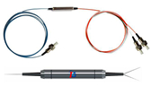
Pump and signal combiner for bi-directional pumping of all-fiber lasers and amplifiers(1)

Abstract

We developed an all-fiber component with a signal feedthrough capable of combining up to 6 fiber-coupled multi-mode pump sources to a maximum pump power of 400 W at efficiencies in the range of 89 to 95%, providing the possibility of transmitting a high power signal in forward and in reverse direction. Hence, the fiber pump combiner can be implemented in almost any fiber laser or amplifier architecture. The complete optical design of the combiner was developed based on ray tracing simulations and confirmed by experimental results.

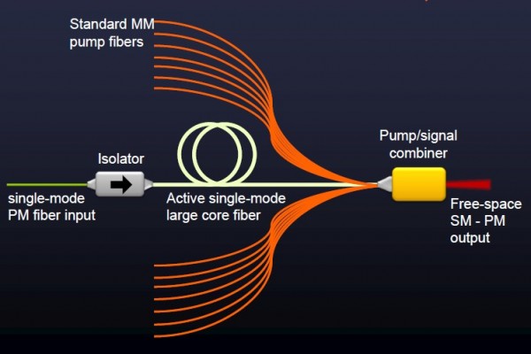
(N+1)X1 Pump and Signal Combiner

1. Introduction

For the realization of compact, reliable, rugged and efficient monolithic high power fiber laser systems, the efforts of integrating all-fiber components have been increased in recent years [1,2]. A key component of a highly integrated fiber laser or amplifier system is a high power all-fiber signal and pump combiner.

The most common type of fiber combiner, a fused tapered fiber bundle (TFB) [3,4], is based on the fiber end face pumping technique and is probably the most sophisticated pump combiner capable of handling several hundred watts of pump power [5]. A TFB with signal feedthrough consists of a central input signal fiber, guiding the signal light, surrounded by several multi-mode fibers, guiding the pump light, and an output pigtail double-clad (DC) fiber which combines the signal and pump light in a single pigtail fiber. In order to match the diameter of the fiber bundle to the diameter of the output pigtail fiber, the bundle is slowly melted and tapered. After the tapering process the fiber bundle is cleaved around the taper waist and fusion spliced to the output pigtail DC fiber. However, tapering of the fiber bundle inherently involves increasing the numerical aperture (NA) of the pump light and a change of the mode field diameter (MFD) of the signal light. Hence, the necessary optical matching and mechanical alignment requirements between the tapered fiber bundle and the output pigtail DC fiber can lead to several drawbacks of the TFB structure: (1) less flexibility in the choice of input fibers that match the output pigtail DC fiber after the tapering process, (2) a slight mismatch or misalignment between the signal mode field diameters (MFD) of the tapered input signal fiber and the output pigtail DC fiber leads to a degradation of the beam quality, primarily in conjunction with signal insertion loss, and (3) in the case of a backward propagating signal, e.g. for a counter-propagation pumped fiber amplifier, the signal insertion loss (up to 10%) can cause damage to the pump diodes due to their insufficient isolation against amplified signal light.

A more promising approach to overcome these problems is side-pumping technology, which involves coupling the pump light via the outermost cladding surface into the fiber. The key advantage of this technology is the uninterrupted signal core, eliminating the need for an additional fusion splice in conjunction with signal mode matching. In recent years several proposals for side-pumping of DC fibers have been reported, such as V-groove side pumping [6], a mirror embedded in the inner cladding of a DC fiber [7] or side-coupling by an angle polished pump fiber [8]. However, for most of these side-pumping configurations it is difficult to reach the mechanical accuracy required for a stable and efficient pump light coupling.

A more rugged approach is a monolithic all-fiber combiner like the GT-Wave coupler [9], the employment of a tapered capillary around a multi-clad fiber [1011] or direct fusion of one or more tapered multi-mode fibers to the outermost cladding of multi-clad fibers [1214]. In Ref [11] seven pump delivery fibers with a core diameter of 110 µm (NA 0.22) were combined and laterally coupled via a tapered capillary into a DC fiber with a core diameter of 400 µm (NA 0.46), which led to a combined pump power of 86 W with a coupling efficiency of ~80%. In Ref [13], direct lateral fusion of one tapered pump delivery fiber with a core diameter of 200 µm (NA 0.46) to a DC fiber of 250 µm (NA 0.46) led to a coupling efficiency of 90% at a pump input power of 120 W, furthermore, a pump delivery fiber with a diameter of 400 µm (NA 0.46) was used to couple a pump power of 300 W with an efficiency of 85% into a DC fiber with a diameter of 400 µm (NA 0.46). These impressive coupling efficiencies for one pump port were achieved by use of a straight and a tapered fiber section, allowing for highly efficient coupling of pump light rays with a high numerical aperture. Thus, in Ref [13] the impact of the straight fiber section on the side-pump coupling process was discussed. However, a review of the literature reveals that the impact of the fiber and taper parameters on the pump coupling behavior as well as the loss mechanism have not yet been investigated in detail for side-pumped combiners based on direct fusion of one or several tapered multi-mode fibers to the outermost cladding of a DC fiber.

We report detailed simulations and experiments for a component which combines up to 6 multi-mode fibers with a core diameter of 105 µm (NA 0.15 or 0.22) into a DC fiber with a cladding diameter of 250 µm (NA 0.46) via side-coupling. Firstly, we explain the principle of the optical design of the fiber combiner. For a fiber combiner with a single pump port, the achievable pump coupling efficiency and the corresponding loss mechanisms were investigated. For multiple pump ports, the simulations and experiments showed that with each additional pump port, the taper parameters need to be adjusted in comparison to a single pump port configuration. These simulation results can also be used as an estimation for fiber combiners, which combine one or several multi-mode fibers with a core diameter of 200 µm (NA 0.22) into a DC fiber with a cladding diameter of 400 µm (NA 0.46). Therefore, this work covers two important fiber combiner types, since active fibers with cladding diameters of 250 or 400 µm are typical sizes provided by fiber manufacturers and used for continuous wave and pulsed laser systems. In addition, we also investigated the signal feedthrough of the combiner. We demonstrated a low signal insertion loss, maintenance of an excellent signal beam quality and an efficient isolation of the pump diodes against signal light in the case of a reverse propagating signal. The preservation of the signal light properties by the fiber combiner was utilized in Ref [15] for the realization of a counter-propagation pumped single-frequency fiber amplifier with an amplified signal power of 300 W.

Comparation Between EPON and GPON

With the continuous progress of science and technology, the Internet has gradually gone into the homes of the ordinary people, and the speed of broadband has increasingly become the topic of people in the entertainment and work often, from narrowband dial-up to broadband Internet, and then the fiber access Internet, broadband network, the rapid pace of PON technology gradually come to the front. Currently, there are two quite compelling PON standard has been officially released, which are GPON standard developed by the ITU / FSAN and EPON standard developed by IEEE 802.3ah working group. PON technology has been no doubt the ultimate solution for the future FTTH era. EPON and GPON who will the dominant FTTH tide has become a new hot debate. What’s the difference between EPON and GPON?

GPON and EPON Differences

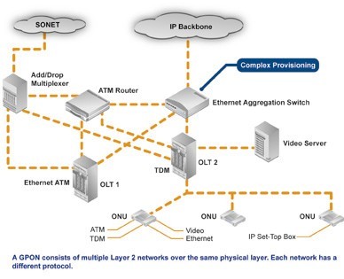
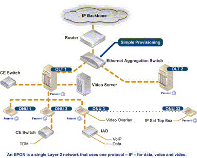
Perhaps the most dramatic distinction between the two protocols is a marked difference in architectural approach. GPON provides three Layer 2 networks: ATM for voice, Ethernet for data, and proprietary encapsulation for voice. EPON, on the other hand, employs a single Layer 2 network that uses IP to carry data, voice, and video.

A multiprotocol transport solution supports the GPON structure (Figure 1). Using ATM technology, virtual circuits are provisioned for different types of services sent from a central office location primarily to business end users. This type of transport provides high-quality service, but involves significant overhead because virtual circuits need to be provisioned for each type of service. Additionally, GPON equipment requires multiple protocol conversions, segmentation and reassembly (SAR), virtual channel (VC) termination and point-to-point protocol (PPP).

Figure 1: Diagram showing a typical GPON network.

EPON provides seamless connectivity for any type of IP-based or other “packetized” “communications” (Figure 2). Since Ethernet devices are ubiquitous from the home network all the way through to regional, national and worldwide backbone networks, implementation of EPONs can be highly cost-effective. Furthermore, based on continuing advances in the transfer rate of Ethernet-based transport — now up to 10 Gigabit Ethernet — EPON service levels for customers are scalable from T1 (1.5 Mbit/s) up through 1 Gbit/s.

Figure 2: Diagram showing a typical EPON network.

Upstream Bandwidth

Subtracting the various system run overhead from the total bandwidth of the system uplink transmission is the upstream available bandwidth. It has a great relationship with the number of the ONU contained in the system, DBA (Dynamic Bandwidth Allocation) algorithm polling cycle, the type of bearer services, as well as the various business proportion. EPON and GPON are broadband access technology, hosted business IP data services. Below we will calculate the uplink the beared pure IP services available bandwidth of EPON and GPON that contain 32 ONUs, fiber optic coupler,the case of polling period 750s.

EPON

EPON upstream rate is 1.25 Gbit/s. Because the 8B/10B line coding, each 10bit are 8bit valid data, so its effective upstream transmission bandwidth is 1 Gbit/s. EPON upstream overhead of running the system and its proportion of the total bandwidth are as following:

1. Used for the the burst reception of physical layer overhead: about 3.5%;

2. Ethernet frame encapsulation overhead: about 7.4%;

3. MPCP (Multi-Point Control Protocol) and OAM operation and management of maintenance protocol overhead: about 2.9%;

4. DBA algorithm resulting in the remaining time slots (that is not sufficient to transfer a complete Ethernet frame time slot) wasted: about 0.6%;

5. EPON upstream total overhead is all of the above about 144 Mbit/s, the available bandwidth is about 856 Mbit/s.

GPON

GPON supports a variety of rate levels, has asymmetric rate that downlink is 2.5Gbps or 1.25Gbps, the upgoing is 1.25Gbps or 622 Mbps. NRZ encoding the uplink total bandwidth for 1.244 Gbit/s, GPON upstream overhead of running the system as following:

1. The proportion of its total bandwidth is used for the the burst reception of physical layer overhead: about 2.0%;

2. GEM (GPON encapsulation method) frame and the Ethernet frame encapsulation overhead: about 5.8%;

3. The PLOAM (physical layer operation, management and maintenance) protocol overhead: about 2.1%;

4. Remaining slots of the DBA algorithm introduced the additional encapsulation overhead: about 0.8%.

5. GPON upstream total overhead is all of the above about 133 Mbit/s, the available bandwidth about 1111 Mbit/s.

What is Passive Optical Network?

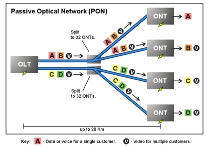
Passive Optical Network (PON) is a form of fiber-optic access network that uses point-to-multipoint fiber to the premises in which unpowered optical splitters are used to enable a single optical fiber to serve multiple premises. A PON system consists of an OLT at the service provider’s central office and a number of ONU units near end users, with an ODN between the OLT and ONU. PON reduces the amount of fiber and central office equipment required compared with point-to-point architectures.

PON Optical Network
Passive Optical Network (PON)

The most obvious advantage of the PON network is the elimination of the outdoor active devices. All the signals processing functions are completed in the switches and the user premises equipment. The upfront investment of this access methods are small, and the most funds investment is postponed until the user really access. Its transmission distance is shorter than the active optical access system. The coverage is also smaller, but it is low cost, no need to set the engine room, and easy to maintain. So this structure can be economically serve for the home users.

PON Development Background

Seen from the entire network structures, due to the larger numbers of laying optical fibers, and widely applications of DWDM technology, the backbone network has been a breakthrough in the development. The same time, due to advances in Ethernet technology, its dominant LAN bandwidth has increased from 10M, 100M to 1G or 10G.. At present, what we are concerned about is the part between the network backbone and local area networks, home users; this is often said that the “last mile”, which a bottleneck is. Must break this bottleneck, may user in the new world of the online world. It is as if in a national highway system, trunk and regional roads have been built in the broad high-grade highway, but leads to the families and businesses of the door was still narrow winding path, the efficiency of the road network cannot play.