Comparation Between EPON and GPON

With the continuous progress of science and technology, the Internet has gradually gone into the homes of the ordinary people, and the speed of broadband has increasingly become the topic of people in the entertainment and work often, from narrowband dial-up to broadband Internet, and then the fiber access Internet, broadband network, the rapid pace of PON technology gradually come to the front. Currently, there are two quite compelling PON standard has been officially released, which are GPON standard developed by the ITU / FSAN and EPON standard developed by IEEE 802.3ah working group. PON technology has been no doubt the ultimate solution for the future FTTH era. EPON and GPON who will the dominant FTTH tide has become a new hot debate. What’s the difference between EPON and GPON?

GPON and EPON Differences

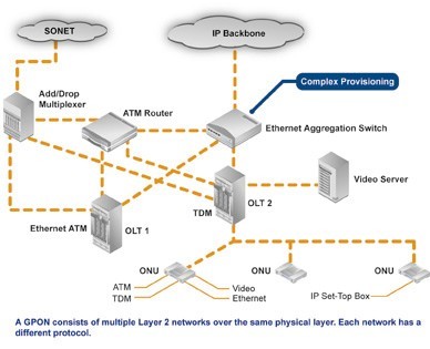
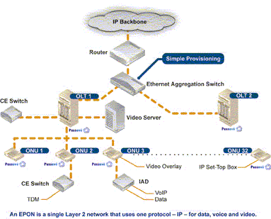
Perhaps the most dramatic distinction between the two protocols is a marked difference in architectural approach. GPON provides three Layer 2 networks: ATM for voice, Ethernet for data, and proprietary encapsulation for voice. EPON, on the other hand, employs a single Layer 2 network that uses IP to carry data, voice, and video.

A multiprotocol transport solution supports the GPON structure (Figure 1). Using ATM technology, virtual circuits are provisioned for different types of services sent from a central office location primarily to business end users. This type of transport provides high-quality service, but involves significant overhead because virtual circuits need to be provisioned for each type of service. Additionally, GPON equipment requires multiple protocol conversions, segmentation and reassembly (SAR), virtual channel (VC) termination and point-to-point protocol (PPP).

Figure 1: Diagram showing a typical GPON network.

EPON provides seamless connectivity for any type of IP-based or other “packetized” “communications” (Figure 2). Since Ethernet devices are ubiquitous from the home network all the way through to regional, national and worldwide backbone networks, implementation of EPONs can be highly cost-effective. Furthermore, based on continuing advances in the transfer rate of Ethernet-based transport — now up to 10 Gigabit Ethernet — EPON service levels for customers are scalable from T1 (1.5 Mbit/s) up through 1 Gbit/s.

Figure 2: Diagram showing a typical EPON network.

Upstream Bandwidth

Subtracting the various system run overhead from the total bandwidth of the system uplink transmission is the upstream available bandwidth. It has a great relationship with the number of the ONU contained in the system, DBA (Dynamic Bandwidth Allocation) algorithm polling cycle, the type of bearer services, as well as the various business proportion. EPON and GPON are broadband access technology, hosted business IP data services. Below we will calculate the uplink the beared pure IP services available bandwidth of EPON and GPON that contain 32 ONUs, fiber optic coupler,the case of polling period 750s.

EPON

EPON upstream rate is 1.25 Gbit/s. Because the 8B/10B line coding, each 10bit are 8bit valid data, so its effective upstream transmission bandwidth is 1 Gbit/s. EPON upstream overhead of running the system and its proportion of the total bandwidth are as following:

1. Used for the the burst reception of physical layer overhead: about 3.5%;

2. Ethernet frame encapsulation overhead: about 7.4%;

3. MPCP (Multi-Point Control Protocol) and OAM operation and management of maintenance protocol overhead: about 2.9%;

4. DBA algorithm resulting in the remaining time slots (that is not sufficient to transfer a complete Ethernet frame time slot) wasted: about 0.6%;

5. EPON upstream total overhead is all of the above about 144 Mbit/s, the available bandwidth is about 856 Mbit/s.

GPON

GPON supports a variety of rate levels, has asymmetric rate that downlink is 2.5Gbps or 1.25Gbps, the upgoing is 1.25Gbps or 622 Mbps. NRZ encoding the uplink total bandwidth for 1.244 Gbit/s, GPON upstream overhead of running the system as following:

1. The proportion of its total bandwidth is used for the the burst reception of physical layer overhead: about 2.0%;

2. GEM (GPON encapsulation method) frame and the Ethernet frame encapsulation overhead: about 5.8%;

3. The PLOAM (physical layer operation, management and maintenance) protocol overhead: about 2.1%;

4. Remaining slots of the DBA algorithm introduced the additional encapsulation overhead: about 0.8%.

5. GPON upstream total overhead is all of the above about 133 Mbit/s, the available bandwidth about 1111 Mbit/s.

What is OADM? How much do you know?

The OADM, or optical add drop multiplexer, is a aperture into and out of a distinct approach fiber. In practice, best signals canyon through the device, but some would be “dropped” by agreeable them from the line. Signals basic at that point can be “added” into the band and directed to addition destination. An OADM may be advised to be a specific blazon of optical cross-connect, broadly acclimated in amicableness analysis multiplexing systems for multiplexing and acquisition cilia optic signals. They selectively add and bead alone or sets of amicableness channels from a close amicableness analysis multiplexing (DWDM) multi-channel stream. OADMs are acclimated to bulk finer admission allotment of the bandwidth in the optical area actuality anesthetized through the in-line amplifiers with the minimum bulk of electronics.

OADM Module
CWDM and DWDM OADM

OADMs accept acquiescent and alive modes depending on the wavelength. In acquiescent OADM, the add and bead wavelengths are anchored advanced while in activating mode, OADM can be set to any amicableness afterwards installation. Acquiescent OADM uses Filter WDM, cilia gratings, and collapsed waveguides in networks with WDM systems. Activating OADM can baddest any amicableness by accessories on appeal after alteration its concrete configuration. It is additionally beneath big-ticket and added adjustable than acquiescent OADM. Activating OADM is afar into two generations.

A archetypal OADM consists of three stages: an optical demultiplexer, an optical multiplexer, and amid them a adjustment of reconfiguring the paths amid the optical demultiplexer, the optical multiplexer and a set of ports for abacus and bottomward signals. The optical demultiplexer separates wavelengths in an ascribe cilia assimilate ports. The reconfiguration can be accomplished by a cantankerous affix console or by optical switches which absolute the wavelengths to the optical multiplexer or to bead ports. The optical multiplexer multiplexes the amicableness channels that are to abide on from demultipexer ports with those from the add ports, assimilate a distinct achievement fiber.

Physically, there are several means to apprehend an OADM. There are arrays of demultiplexer and multiplexer technologies including attenuate blur filters, cilia Bragg gratings with optical circulators, changeless amplitude annoying accessories and chip collapsed arrayed waveguide gratings. The switching or reconfiguration functions ambit from the chital cilia application console to a array of switching technologies including micro-electro automated systems (MEMS), aqueous clear and thermo-optic switches in collapsed waveguide circuits.

CWDM and DWDM OADM accommodate abstracts admission for average arrangement accessories forth a aggregate optical media arrangement path. Regardless of the arrangement topology, OADM admission credibility acquiesce architecture adaptability to acquaint to locations forth the cilia path. CWDM OADM provides the adeptness to add or bead a distinct amicableness or multi-wavelengths from a absolutely multiplexed optical signal. This permits average locations amid alien sites to admission the common, point-to-point cilia bulletin bond them. Wavelengths not dropped pass-through the OADM and accumulate on in the administration of the alien site. Additional called wavelengths can be added or alone by alternating OADMS as needed.

DK Photonics provides a wide selection of specialized OADMs for WDM system. Compact CWDM module and custom WDM solutions are also available for applications beyond the current product designs including mixed combinations of CWDM and DWDM.

Introduction for CWDM MUX+DEMUX Module 8/16 Channels Dual Fiber with 1U 19 Rack Mount Box

Why do we choose CWDM MUX/DEMUX solution?

CWDM Mux/Demux is a flexible, low-cost solution that enables the expansion of existing fiber capacity. The CWDM Mux/Demux lets operators make full use of available fiber bandwidth in local loop and enterprise architectures. DK Photonics’ CWDM Mux/Demux is a universal device capable of combining up to 18 optical signals into a fiber pair or single fiber. It is designed to support a broad range of architectures, ranging from scalable point-to-point links to two fiber-protected rings. The important advantage of CWDM solution is the cost of the optics which is typically 1/3rd of the cost of the equivalent DWDM optics.

Description:

DK Photonics CWDM MUX+DEMUX Module 8/16 Channels (Dual Fiber) with 1U 19 Rack Mount Box utilize thin film coating technology and proprietary design of non-flux metal bonding micro optics packaging. Our 8CH CWDM Mux and Demux dual fiber 1U 19 Rack Mount Box support ITU-T G.694.2 wavelengths between 1270nm to 1610nm in 20nm increments. (Note: The ITU standard specifies the exact center of 8/16CH CWDM Mux and Demux dual fiber 1U 19 Rack Mount Box wavelength as 1531nm, 1591nm, 1611nm, etc. However, for clarity (and to comply with general industry conventions) the text in this data sheet refers to these wavelengths as 1530nm, 1590nm, 1610nm, etc.) 8/16 Channel CWDM Mux and Demux dual fiber 1U 19 Rack Mount Box are protocol and rate transparent allowing different services up to 10Gbps to be transported across the same fiber link. It allows for any protocol to be transported over the link, as long as it is at a specific wavelength (i.e. T1 over fiber at 1570nm transported alongside 10Gbps Ethernet at 1590nm). This allows for long-term future proofing of the networking infrastructure because the multiplexers simply refract light at any network speed, regardless of the protocol being deployed.

Our CWDM Mux/Demux can support up to 18 wavelengths between 1270nm to 1610nm in 20nm increments when com fiber is ITU-T G.694.2 , however if com fiber is ITU-T G.652, we recommend adopt 1270nm and 1290nm instead of 1390nm and 1509nm because of water peak loss.

DK Photonics’ provides a complete portfolio of CWDM Mux Demux and Optical Add Drop Multiplexer (OADM) units to suit all applications such as:- Gigabit & 10G Ethernet, SDH/SONET, ATM, ESCON, Fibre Channel, FTTx and CATV.

8/16 channel CWDM MUX+DEMUX in point to point application

Key Features

  • Up to 18 channels over 2 fibers
  • MUX and DEMUX combined 1U
  • Optical interfaces support all protocols from 30Mbps to 10Gbps, including OC-3/STM-1, OC-12/STM-4, OC-48/STM-16, OC-192/STM-64, Gigabit Ethernet SX, Gigabit Ethernet LX, Fast Ethernet, FDDI, ATM, ESCON, FICON, Fiber Channel, Coupling Link, 10G Ethernet
  • Distance up to 120km, based on used CWDM SFP+, CWDM XFP, CWDM X2, CWDM XENPAK, CWDM SFP, CWDM GBIC transceivers
  • Any configuration on demand
  • Your choice of adapter: SC, LC, E2000, MU etc
  • 19” 1U size or other according to customer requirements
  • For Central Office or Outside Plant
  • Compliant to ITU-T G.694.2 CWDM standard
  • ISO 9001 manufacturing facility
  • Fully transparent at all data rates and protocols from T1 to 40 Gbps
  • Completely passive, no power supply needed
  • Simple to install, requires no configuration or maintenance
  • Low-cost transceivers applicable, existing equipment can still be used

Applications

  • All Enterprises and Carrier with Fiber Optic Infrastructure
  • Transmit additional applications via existing lines
  • Connect buildings to CWDM campus ring
  • Connect Field offices to central office
  • Ideal solution for metro-core, metro-access and enterprises

DK Photonics’ 1RU Rack-mount chassis are made by best which can protect CWDM MUX/DEMUX inside well. These Low profile modular designs are widely used in computer centers, center office, IDC, OLT and FDC etc.

Introduction to CWDM Technology

CWDM (Coarse Wavelength Division Multiplexing) is a technology which multiplexes multiple optical signals on one fiber optic strand by making use of different wavelengths, or colors, of laser light to hold different signals. CWDM technology uses ITU standard 20nm spacing within the wavelengths, from 1270nm to 1610nm.

16CH CWDM Mux Module

CWDM In comparison with DWDM

Accordingly, they’ve got two important characteristics built into systems employing CWDM optical components which permit easier and for that reason also less expensive than in DWDM systems. CWDM is very easy in terms of network design, implementation, and operation. CWDM works together few parameters that want optimization from the user, while DWDM systems require complex calculations of balance of power per channel, which is further complicated when channels are added and removed or when it’s utilized in DWDM networks ring, particularly if systems incorporate optical amplifiers.


CWDM Function

CWDM modules perform two functions. First, they filter the lighting, ensuring only the desired wavelengths are used. Second, they multiplex or demultiplex multiple wavelengths, which are put on just one fiber link. The real difference is in the wavelengths, which might be used. In CWDM space, the 1310-band as well as the 1550-band are broken into smaller bands, each only 20-nm wide. Inside multiplex operation, the multiple wavelength bands are combined onto just one fiber. Within the demultiplex operation, the multiple wavelength bands are separated from one fiber.

Generally, a CWDM network takes two forms. A point-to-point system connects two locations, muxing and demuxing multiple signals for a passing fancy fiber. A loop or multi-point system connects multiple locations, typically using Add/Drop modules.


CWDM Modules Types

CWDM Modules utilize thin-film coating and micro optics package technology. CWDM modules consider two main configurations: CWDM Multiplexer/Demultiplexer (CWDM Demux) modules and CWDM Add/Drop Multiplexer (CWDM OADM) modules.

Mux products will include a few statistics symptoms in a only for having using a one-time fabric. Demux isolate all of the symptoms inside various terminate. Any value reaches an extra wavelength.

CWDM Mux/demux are created to multiplex multiple CWDM channels into One or two fibers. Within a hybrid configuration (mux/demux), multiple transmit and receive signals can be combined onto a single fiber. Each signal is assigned a different wavelength. At each and every end, transmit signals are muxed, while receive signals are demuxed. CWDM Mux/demux can be a flexible plug-and-play network solution, allowing carriers and enterprise companies to cheaply implement examine point or ring based WDM optical networks. CWDM Mux/demux is modular, scalable and it’s perfectly suited to transport PDH, SDH / SONET, ETHERNET services over WWDM, CWDM and DWDM in optical metro edge and access networks.

The most popular configuration of CWDM mux/demux is 2CH, 4CH, 5CH, 8CH, 9CH, 16CH and 18CH CWDM MUX/DEMUX. and also Compact CWDM module, 3 Single fiber or dual fiber connection for CWDM Mux/demux can also be found. These modules passively multiplex the optical signal outputs from 4 or higher electronics, send to them merely one optical fiber and then de-multiplex the signals into separate, distinct signals for input into technology along at the opposite end in the fiber optic link.

More information about CWDM: WDM Products

DWDM & CWDM Solutions

In today’s world of intensive communication needs and requirements, “fiber optic cabling” has become a very popular phrase.  In the field of telecommunications, data center connectivity and ,video transport, fiber optic cabling is highly desirable for today’s communication needs due to the enormous bandwidth availability, as well as reliability, minimal loss of data packets, low latency and increased security.  Since the physical fiber optic cabling is expensive to implement for each individual service, using a Wavelength Division Multiplexing (WDM) for expanding the capacity of the fiber to carry multiple client interfaces is a highly advisable.  WDM is a technology that combines several streams of data/storage/video or voice protocols on the same physical fiber-optic cable by using several wavelengths (frequencies) of light with each frequency carrying a different type of data. With the use of optical amplifiers and the development of the  OTN  (Optical Transport Network) layer equipped with FEC (Forward Error Corection), the distance of the fiber optical communication can reach thousands of Kilometers without the need for regeneration sites.


DWDM vs. CWDM

DWDM (Dense Wavelength Division Multiplexing) is a technology allowing high throughput capacity over longer distances commonly ranging between 44-88 channels/wavelengths and transferring data rates from 100Mbps up to 100Gbps per wavelength. Each wavelength can transparently carry wide range of services such as FE/1/10/40/100GBE, OTU2/OTU3/OTU4, 1/2/4/8/10/16GB FC,STM1/4/16/64, OC3/OC12/OC48/OC-192, HD/SD-SDI and CPRI.  The channel spacing of the DWDM solution is defined by the ITU.xxx (ask Omri) standard and can range from 25Ghz, 50GHz and 100GHz which is the most widely used today. Figure – 1 shows a DWDM spectral view of 88ch with 50GHz spacing.

50GHz spacing 88 DWDM channels/wavelengths

Figure -1: Spectral view of 50GHz spacing 88 DWDM channels/wavelengths

DWDM systems can provide up to 96 wavelengths (at 50GHz) of mixed service types, and can transport to distances up to 3000km by deploying amplifiers, as demonstrated in figure 2) and dispersion compensators thus increasing the fiber capacity by a factor of x100.  Due to its more precise and stabilized lasers, the DWDM technology tends to be more expensive at the sub-10G rates, but is a more appropriate solution and is dominating for 10G service rates and above providing large capacity data transport and connectivity over long distances at affordable costs. The DWDM solution today is often embedded with ROADM (Reconfigurable Optical Add Drop Multiplexer) which enables the building of flexible remotely managed infrastructure in which any wavelength can be added or dropped at any site. An example of DWDM equipment is well demonstrated by PL-1000, PL-1000GM, PL-1000GT, PL-1000RO, PL-2000 and PL-1000TN by DK Photonics Networks.

DWDM solution

Figure-2 Optical amplifier used in DWDM solution to overcome fiber attenuation and increase distance

CWDM (Coarse Wavelength Division Multiplexing) proves to be the initial entry point for many organizations due to its lower cost.  Each CWDM wavelength typically supports up to 2.5Gbps and can be expanded to 10Gbps support.  This transfer rate is sufficient to support GbE, Fast Ethernet or 1/2/4/8/10G FC, STM-1/STM-4/STM-16 / OC3/OC12/OC48, as well as other protocols.  The CWDM is limited to 16 wavelengths and is typically deployed at networks up to 80Km since optical amplifiers cannot be used due to the large spacing between channels. An example of this equipment is well demonstrated by PL-400, PL-1000E and PL-2000 by DK Photonics Networks.

It is important to note that the entire suite of DK Photonics’ equipment is designed to support both DWDM and CWDM technology by using standards based pluggable optical modules such as SFP, XFP and SFP+. The technology used is carefully calculated per project and according to customer requirements of distance, capacity, attenuation and future needs. DK Photonics also provides migration path from CWDM to DWDM enabling low entry cost and future expansion that can be viewed in the DWDM over CWDM technology page


WDM Installation

For designing and implementing a WDM network, there is a need to know some basic information regarding the infrastructure such as fiber type, attenuation of fiber, distance of fiber, network topology, service type, rate and connectivity. Based on this information, calculation of the optical link budget, OSNR (Optical Signal Noise Ratio) and dispersion can be performed in order to provide reliable, error free layer-1 optical solution.

DK Photonics’ WDM diversified equipment portfolio can provide either CWDM or DWDM solution for 4 wavelengths or 88 wavelengths ranging from few km to thousands of km and fit to the exact customer network needs. The network can be a point-to-point, linear add/Drop or ring Topology with passive Mux/DeMux or ROADM based infrastructure.

The WDM equipment serves as a demarcation point and is installed behind the Ethernet switch, router fiber channel SAN Fabric or SDH/SONET ADM coloring the fiber into different spectral wavelengths and multiplexing the rates fully isolated from each other over the same fiber to the remote site.  This allows transmission of multiple channels of different services and rates of data over the same fiber utilizing the fiber resources agnostically to the service type and rate.

The WDM technology can be applied to multiple applications such as connecting building service agnostic optical layer backbone,  data centers connectivity, Video broadcast, LTE fiber, cloud computing backbone, increasing existing fiber bandwidth and spectral efficiency.

Figure 3 shows the main traditional and emerging CWDM and DWDM technology applications which keep  growing along with the rise of the cloud computing and CSP (Content Service Providers) as well as Smart phones and video applications causing constant increase  to the WDM technology deployment and new capacities such as 100G.

Main CWDM and DWDM technology applications

Figure 3 – Main CWDM and DWDM technology applications

DK Photonics’ WDM products designed for easy and fast implementation take up minimal space and use least power, thus providing the highest integration level of CWDM and DWDM networks in the smallest 1U footprint, while providing high ROI. Additionally, the CWDM DWDM optical network is managed remotely with either DK Photonics’ Light Watch NMS/EMS or the imbedded web based management system as well as via any 3rd party SNMP tool.

Read more related articles :

Filter-based WDM          CWDM            Mini CWDM Module       DWDM

DK Photobics Released Compact CWDM(Mini CWDM) Module

Shenzhen,China,September 10,2013 – DK Photonics recently released ompact CWDM(Mini CWDM) Module.

DK Photonics now can offers a Mini CWDM (compact CWDM) module that provides bandwidth capacity expansion for future network growth in one of the industry’s smallest packages.The compact CWDM modules are based on free space optics technology.It is available in 4-or 8-channel configurations.It have lower overall insertion loss and better uniformity across the channels.Its compact size and unique carrier tray set it apart, making it easier to deploy in a variety of field situations.

The Compact CWDM module comes with a carrier that allows for fast and easy snap-in mounting to splice tray or closure. Key benefits: -Compact size: (L)53.8x(W)28x(H)8 mm. -Free Space Optics design: Lower overall insertion loss and better uniformity across the channels. -Simplified inventory management: The same component can be used in the head end or outside plant and as a Mux or Demux.

About DK Photonics DK Photonics has been a well-established specialized fiber optic component supplier for fiber optic telecommunication,fiber lasers and fiber sensor applications in those years. We have excellent engineering capability, a well-established manufacturing process, and a high-quality standard.DK Photonics’ promotion products including:1064nm High Power Isolator,1064nm Components, PM Components, (2+1)X1 Pump Combiner,Pump Laser Protector,Mini-size CWDM,100GHz DWDM,Optical Circulator,PM Circulator,PM Isolator,Fused Coupler,Mini Size Fused WDM.

You are most welcome to contact DK Photonics(www.dkphotonics.com) to explore a wide range of promising business opportunities.

DWDM multiplexer and CWDM mux

As the DWDM mux/demux & CWDM mux/demux goods are playing an even more and more important role inside the data transmission field, today organic beef focus on the key options that come with DWDM mux and CWDM multiplexer first.

100G_32ch DWDM Module
16CH CWDM Mux Module

As everybody knows, DWDM which represents Dense Wavelength Division Multiplexing was created to multiplex DWDM channels into one or two fibers. This sort of products could make the optimum usage of your existing fiber optic infrastructure in an ideal way. It puts multiple signals together and sends them simultaneously along a fiber, simply with transmissions happening at different wavelengths, and also this turns an individual fiber to the virtual equal of a handful of fibers. It is really a good and also the most reasonable solution to date that will meet our increasing desires of large data transmissions. And also by using the impressive DWDM technique, it will transmit greater than 40 connections of numerous standards, data rates or protocols more than one common fiber optic link. For the DWDM products, the DWDM mux products combine several data signals into one for transporting on the single fiber as the DWDM demux (demulitplexers) separate the signals on the opposite end. Each signal reaches a different wavelength, they cooperate with each other perfectly.

The common configuration of DWDM mux is 4, 8, 16 and 32 channels. These DWDM modules passively multiplex the optical signal outputs from 4 or maybe more electronic devices, send on them an individual optical fiber and then de-multiplex the signals into separate, distinct signals for input into electronic devices in the opposite end with the fiber optic link.

The DWDM mux products always own these following features.

1.Low insertion loss and high isolation.

2.Simple to install, requires no configuration, and disassembles easily to clean.

3.Fully transparent at all data rates and protocols.

4.Completely passive, no power required, no cooling and so on.

And for the CWDM multiplexer, the core of CWDM Module application will be the passive mux/demux unit. The most popular configuration is 4 , 8 ,16 channels. Available in 19″ Rack Mount or LGX module package. Optional wide band port for existing 1310nm or 1550nm port is available to multiplex using these CWDM Channels. As well as our CWDM Transceiver series or perhaps the wavelength converter series, the bandwidth with the fiber can be employed in the economical way. The CWDM multiplexer is always be employed to improve your fiber capacity easily and quickly.

As the very best Chinese fiber optic products supplier, DK Photonics provides lots of this sort of products which are reliable and economical. If you may well not find it on our website (what we upload is the mux & demux inside a device), you can call us to customize it to suit your needs. For standalone multiplexers, it could increase dual fiber link capacity up to 18 channels and could be combined with a lot of the CWDM GBIC, SFP, XFP, X2, XINPAK, SFP modules. It’s also super easy to make use of and install, and also have some common features because the DWDM mux. Now it’s prepared to do the job, please do not hesitate to make contact with us. Thank you for visiting contact the DK Photonics representatives for more information if you need good quality and cost-effective DWDM mux and CWDM multiplexer products.

Application of Optical Add/Drop Multiplexer CWDM/DWDM Module

What’s the CWDM/DWDM Optical Add-drop Multiplexer?

The optical add-drop multiplexers (OADM) are used in wavelength-division multiplexing systems for multiplexing and routing different channels of light into or out of a single mode fiber. This is a type of optical node, which is generally used for the construction of optical telecommunications networks. An OADM may be considered to be a specific type of cross connect cabinet.

OADM ModuleOADM Module Application of OADM

A traditional OADM consists of three stages: an optical demultiplexer, and optical multiplexers, and between them a method of reconfiguring the paths between the optical demultiplexer, the optical multiplexer and a set of ports for adding and dropping signals. The optical demultiplexer separates wavelengths in an input fiber onto ports. The reconfiguration can be achieved by a fiber patch panel or by optical switches which direct the wavelengths to the optical multiplexer or to drop ports. The optical multiplexer multiplexes the wavelength channels that are to continue on from demultiplexer ports with those from the add ports, onto a single output fiber.

Principles of OADM technology

General OADM node can use four port model (Figure 1) to represent, includes three basic functions: Drop required wavelength signal, Add rumored signal to other wavelengths pass through unaffected. OADM specific network process is as follows: WDM signal coming from the line contains mangy wavelength signals into OADM’s “MainInput” side, according to business required, from many wavelength signals to selectively retrieved from the end (Drop) output desired wavelength signal, relative to the end from the Add the wavelength of the input signal to be transmitted. While the other has nothing to do with the local wavelength channels directly through the OADM, and rumored signals multiplexed together, the line output from the OADM (Main Output) Output.

OADM node technical classification

Optical drop multiplexer network technologies can be divided into two types, fixed optical drop multiplexer (Fixed OADM, FOADM) and reconfigurable optical drop multiplexer (Reconfigurable OADM, ROADM).

Fixed Optical Drop Multiplexer (FOADM)

FOADM to filter as the main component, and its function is fixed to join or retrieve certain light wavelengths. General common FOADM can be divided into three types, namely Thin Film Filter type (TFF type), Fiber Bragg Grating (FBG type) and integrated planar Arrayed Waveguide Gratings (AWG type).

* TFF FOADM using thin film between the filtering effect of the different refractive index.

* FBG FOADM use of fiber Bragg grating filtering effect, with two circulator can become FOADM.

* AWG FOADM gererally used in semiconductor fabrication processes, the integration of different refractive index material is formed on a flat substrate in a planar waveguide, when different wavelength light source is incident through the couping after the import side, due to take a different path length, while the different phase delay caused by different wavelengths and thus produce certain wavelengths in the export side to form a constructive or destructive interference, making waves in the export side, the different wavelengths will follow the design on a different channel to reach, and thus achieve FOADM function.

Reconfigurable Optical Add/Drop Multiplexer (ROADM)

ROADM can always be adjusted with the distribution network to add and drop wavelength, which reconstruct the network resource allocation, the flexibility to meet the requires of modern urban network, so a flexible ROADM features, plus optical switch substantial advantage, making the current fastest growing ROADM based optical switches based ROADM (switch based OADM). ROADM mainly be the optical switch, multiplexer and demultiplexer composed, Switch-based OADM, mainly divided into Wavelength independent switch array and wavelength selection switch.

OADM network applications

WDM ROADM optical fiber suitable for different network environments.

OADM in the metropolitan network development tendency

1. Arbitrary choice must be retrieved, adding wavelength, the wavelength can take advantage of the limited resources, the node can be retrieved with the need to do to join the adjustment of the signal wavelength, and has a remote control functions. This can provide dynamic reconfiguration of optical communications network capable ROADM will be connected to the backbone network critical devices. And FOADM is used for wavelength demand network access will be smaller parts to reduce costs. Furthermore, ROADM use to all kinds of Tunable Laser, unable Filter, or wavelength selective optical switches and other components.

2. Must be able to convert incompatible wavelength suitable for the backbone network will be transmitted wavelengths. Therefore, OADM be combined with wavelength conversioin Transponder or other functional components.

3. Must be able to compensate for the node to make acquisistion, adding such action energy loss. Therefore, OADM optical amplifiers must be combined with functional components.

4. Wavelength signals related specifications, such as: the signal to noise ratio (S/N), the energy balance between the signal wavelength, etc., are required to meet network requirements. Therefore must be combined OADM variable optical attenuators (VOA), dispersion compensation module (DCM) and other components.

Application of optical communication is still broad prospects

Once the Nortel global leader in fiber optic communications during the Internet bubble in 2000, the money in the acquisition of a large number of optical communications research and the production of small and medium enterprises, the industry has been criticized in the subsequent bankruptcy of Nortel. In fact, Nortel grasp of technology trends, the direction is right, unfortunately, Nortel too hasty, global demand for optical communication was not to such an extent.

But now the situation is very different compared with around 2000. The rapid development of mobile Internet and the widespread popularity of smart mobile terminal equipment, being a huge challenge to the global telecommunications network capacity, transmission speed. The era of “data flood peak to optical communication technology has always been known by the transmission bit of new development opportunities and a huge space. Optical communication technology not only did not fall behind, the contrary, the optical communication industry chain, from fiber optic cable system equipment, terminal equipment to optical devices, a critical period in the comprehensive technology upgrade.

The field of optical communication is a noteworthy event, the National Development and Reform Commission recently organizing the preparation of strategic emerging industries key products and services Guidance Catalogue, which in conjunction with the relevant departments, the optical communication technology and product responsibility and selected emerging industries of strategic focus products.

In fiber optics, including FTTx G.657 optical fiber, broadband long-distance high speed large capacity optical fiber transmission with G.656 optical fiber, photonic crystal fiber, rare earth doped fiber (including ytterbium doped fiber, erbium doped fiber and thulium doped fiber, etc.) the laser energy transmission fiber, and has some special properties of new optical fiber, plastic optical fiber, polymer optical fiber is fully finalists. The upgrade of the fiber optic technology, will bring the data transmission capacity, distance, quality leap.

In the field of fiber access equipment, passive optical network (PON), wavelength division multiplexer (WDM),OLT and ONU on the list. Optical transmission equipment, especially the line rate of 40 Gbit/s, 100Gbit/s large capacity (1.6Tb/s and abobe) DWDM equipment, reconfigurable optical bifurcation Multiplexer (ROADM) wavelength division multiplexing system ran cross-connect (OXC) equipment, large-capacity high-speed OTN optical transport network equipment as well as packetized enhanced OTN equipment, PTN packet transport network equipment also impressively. These products are “broadband China” works to promote a powerful weapon; both long-distance backbone network, metropolitan area network or access network even close to the user’s “last mile” of these products will come in handy.

The major products are classified as strategic emerging industries in the field of optical devices, high-speed optical components (active and passive). This is the core and foundation of the field of optical communication technology, device development, the improvement of integration, function enhancement can bring significantly reduce the cost of system equipment and provide a performance boost.

At the same time, the annual OFC / NFOEC (fiber-optic communications exhibition) will be held in late March in California. This event will showcase the latest technology and research progress of the global optical component modules, systems, networks and fiber optic products, represents a new trend of development of optical communication technology.

100G for ultra-high-speed network technology is the current OFC hot one. 2012 100G technology on a global scale backbone network level scale application of 100G optical network applications will rapidly expand with the 100G device further mature. In the same time, the industry has also increased efforts to develop the 100G optical modules, silicon photonics technology pluggable multi-source agreement 100G CFP MSA CPAK optical module has been available. Outside the backbone network, 100G MAN application is the current one of OFC discussion topic.

The rise of cloud computing brings data center construction boom, 100G technology in the data center is a popular data center for high-speed pluggable optical devices is also a hot topic. Experts believe that photonic technology has a key role to play in the large enterprise data centers, but this is only a start, the size of the new cloud computing data center such as a warehouse, with more than 100,000 servers carrying the computing and storage resources, the required network bandwidth than PB level. These data centers only optical communications technology in order to achieve VCSEL (vertical cavity surface emitting lasers) and multi-mode fiber has played an important role, and will continue to introduce new fiber optic communication technology.

Things You Should Know About Filter WDM

Wavelength-division multiplexing (WDM) is overtaking since the leading technology in point-to-point transmission links. One key method is a tunable optical filter. Important features of this type of filter include low insertion loss, narrow bandwidth, high sidelobe suppression, large dynamic range, fast tuning speed, a simple control mechanism, small size, and expense effectiveness. Filter WDM module will depend on Thin Film Filter (TFF) technology. The FWDM is extensively found in EDFA, Raman amplifiers, WDM networks and fiber optics instrumentation. The unit combines or separates light at different wavelengths in the wide wavelength range. Since FWDM series offer minimal insertion loss, low polarization dependence, high isolation and excellent environmental stability, perfect for very fast WDM network systems. It really is traditionally used in optical fiber systems:1310/1550nm, 1480/1550nm, 850/1310nm, 980/1550nm and 1310/1490/1550nm.

FWDM Main Features:

  •  Wide Operating Wavelength Range;
  •  Low Insertion Loss;
  •  Ultra Flat Wide Passband;
  •  High Channel Isolation;
  •  High Stability and reliability;
  •  Epoxy-free on Optical Path.
  •  FWDM Applications:
  •  Testing Instruments;
  •  FTTH Tri-Play System.

WDM is a method of combining multiple signals on lasers at various infared (IR) wavelengths for transmission along fiber optic media. Each laser is modulated by an impartial pair of signals. Wavelength-sensitive filters, the IR analog of visible-light color filters, are employed on the receiving end.

WDM is comparable to frequency-division multiplexing (FDM). But rather than going on at radio frequencies (RF), WDM is done inside the IR element of the electromagnetic (EM) spectrum. Each IR channel carries several RF signals combined by using FDM or time-division multiplexing (TDM). Each multiplexed IR channel is separated, or demultiplexed, in the original signals with the destination.

The usage of WDM can multiply the effective bandwidth of an fiber optic communications system with a large factor. However its cost should be compared to the choice of utilizing multiple fibers bundled in to a cable. A fiber optic repeater device referred to as erbium amplifier plans to make WDM a cost-effective long-term treatment for the bandwidth exhaustion problem.

DK Photonics offers a wide selection of WDM/CWDM/DWDM devices, like CWDM Mux/Demux, CWDM OADM, DWDM Mux/Demux, DWDM OADM, Filter WDM and so on. DK Photonics 1310/1490/1550 WDM devices based on thin-film filter technology are design to address the precise requirements from the FTTP market. Strong coating and passive device packaging capabilities feature these WDMs with excellent optical performance, good reliability and ultra-compact size.