Pump and signal combiner for bi-directional pumping of all-fiber lasers and amplifiers(5)

4.3 Simulations for the loss mechanism of the fiber combiner

As already discussed in Section 2, the total 1064nm high power isolator loss is the sum of TP, PAA and PCT (Fig. 1). In this section we will quantitatively determine the power fraction of the different loss mechanisms to gain a better estimate of the resulting thermal load of the fiber combiner. To understand this approach, we first discuss the effect of the different loss mechanisms. The TP pump power loss is less critical, because this power fraction can be easily removed from the fiber component via the IF. The PAA is also less critical, since this power fraction can be handled by an air or 100W 1064nm high power isolator housing. The most critical pump power loss, PCT, is caused by NA-mismatched light, which couples into the coating of the TF and damages the fiber coating at a certain power level.

The loss mechanism and the total pump power loss of the fiber combiner

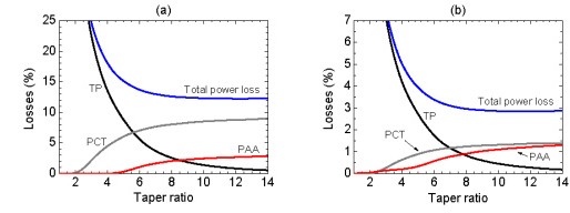
Fig. 4 The loss mechanism and the total pump power loss of the fiber combiner for (a) a TL of 5 mm and (b) a TL of 20 mm at different taper ratios. The losses in percent were calculated with respect to the total input pump power. Please see Fig. 1 for TP, PCT and PAA.

and 4(b) shows the three different pump power losses (TP, PAA, PCT) and the total pump power loss as a percentage of the input pump power for TL of 5 and 20 mm, depending on the TR. In the simulations the core NA of the PFF was 0.22 and fully filled pump light condition of the PFF core was assumed. It should be noted that for comparison, the axis of ordinates in Figs. 4(a) and 4(b)are scaled differently for a more comprehensive presentation of the results. In general, it can be seen that the total and individual losses are larger for a TL of 5 mm compared to a TL of 20 mm. For both TLs it turns out that the TP-fraction decreases and the PCT-fraction as well as the PAA-fraction increases with TR. As a result, the total power loss decreases with increasing TR. A closer analysis of the PCT-curve reveals that PCT loss does not exist below a TR of 2, since the 3 Port Polarization Maintaining Optical Circulator input NA of 0.22 will be approximately increased by the factor of the TR [18], and therefore cannot exceed the cladding NA of the TF of 0.46. Thus, the fraction of PCT can be reduced by choosing a low TR with a still acceptable total power loss. This means that the TR must be carefully adapted to satisfy the trade-off between a high pump coupling efficiency and a low power fraction of PCT to avoid optically induced damage of the fiber component during high power operation. This must always be accompanied by a sufficient converging taper length.

For example, if the TR is set to 7 for a TL of 5 and 20 mm, respectively, the theoretical PCT is 7.7 and 1.2% of the input pump power. The PCT value of 1.2% at a TL of 20 mm can be further reduced to 0.6% by changing the TR from 7 to 4 in conjunction with an acceptable total power loss of just 5%. Hence, if 1 kW of input pump power is assumed, the resulting power handling for the coating of the TF and the pump light stripper can be reduced from 77 W (TL 5 mm, TR 6) to 6 W (TL 20 mm, TR 4) by adapting the TL and the TR.

The simulations indicate that the minimum total power loss cannot be reduced below 2.7% for a TL greater than 20 mm up to a TL of 50 mm and a FL of 1.99. One reason for the residual losses can be pump light rays with a Polarization Maintaining Fused Coupler, which propagate along an unfavorable plane of the IF and do not enter the fusion zone. These rays leave the waveguide (PAA) structure after sufficient bounces along the lateral taper surface. In addition, rays with an extremely low NA, and consequently less bounces with the lateral surface of the converging taper portion, can occur in the form of TP. Furthermore, longer TLs lead to an increased probability that some rays will reverse couple from the TF into the IF.

Moreover, the simulations reveal that a lower FL-value, which means stronger fusing of the fibers, leads to a decrease of the total power loss. The exact reduction of the total power loss depends on the fiber and taper parameters. For a TL of 20 mm and a TR of 6, the simulated total power losses could be reduced from 4% to 2% when decreasing the FL from 1.99 to 1.93. The simulations indicate that for FLs below 1.93 the total power loss increase again.

4.3.1 Impact of pump light input NA on the power leakage into the coating of the TF (PCT)

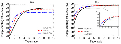
The simulations in Section 4.2, Fig. 3(b) showed that a sufficient TL leads to pump coupling efficiencies of more than 90%, almost independent of the pump light input NA. Considering the losses, the simulation also shows that the PCT-fraction is strongly influenced by the pump light input NA. Figure 5

Fig. 5 

The ratio of power leakage into the cladding of the target fiber

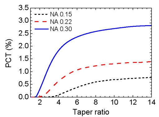
(PCT) to the total input pump power against the taper ratio for a TL of 20 mm.

clearly reveals that for a TL of 20 mm and a TR of 6, the PCT-fraction increases by about 6 times for a NA of 0.3 compared to a NA of 0.15. Hence, it is possible to achieve almost the same coupling efficiency for a pump light input NA of 0.15 and 0.3 (see Fig. 3(b)), but with a significant difference in risk of optically induced damage to the fiber component. However, PCT can be further reduced by increasing the TL.

Pump and signal combiner for bi-directional pumping of all-fiber lasers and amplifiers(4)

4. Simulations and experiments for a fiber combiner with a single pump port

The ray tracing simulations were carried out with the commercially available software Zemax (Radiant Zemax, LLC) in the non-sequential mode. Detailed information about ray tracing in tapered cylindrical fibers can be found in Ref [16] and [17]. The ray tracing method is applicable due to the large cross sections of the employed fibers compared to the applied wavelength of 976 nm. The 3-dimensional simulation model of the fiber combiner was based on the setup depicted in Fig. 1 with the approximation of a parallel fiber arrangement of the IF and TF. For the PFF a fully filled condition was always assumed, meaning that all possible pump light rays, independent of the NA and the transversal position in the fiber core, carry equal power. For the geometrical shape of the taper in the longitudinal direction, a simplified linear shape was assumed in the simulations, instead of the measured parabolic shape. As already mentioned, the FL was set to 1.99. 

4.1 Simulations of the pump coupling efficiency

The pump coupling efficiency in dependence of the converging taper length (TL) and the taper ratio (TR) of the IF for a 1064nm high power isolator with an NA of 0.22 is depicted in Fig. 2(a)

pump coupling efficiency

Fig. 2 (a) Pump coupling efficiency (CE) with respect to the taper ratio (TR) and the converging taper length (TL) and (b) a comparison of the pump coupling efficiencies without intermediate fiber (IF) and with IF for different fiber parameters, IF Ø: IF cladding diameter.

. The simulations show that an increasing TL leads to higher coupling efficiencies at a constant TR. For example at a constant TR of 6 a TL of 5 mm leads to a theoretical maximum pump coupler coupling efficiency of 86%, whereas for a TL of 20 mm 96.4% were calculated. Furthermore, Fig. 2(a) shows that the TR can be reduced, if the TL is increased to maintain a certain coupling efficiency level. For instance, for a TL of 20 mm, a coupling efficiency of 85% can already be obtained at a TR of 2 instead of a TR of 5.5 at a TL of 5 mm. The improved coupling behavior at longer TLs can be explained by the increasing number of bounces of the pump light rays at the lateral surface of the converging taper portion. Hence, for shorter TLs it is necessary to taper more than for longer TLs in order to compensate for the shorter interaction length of the converging taper portion with the TF. The maximum theoretically obtainable pump coupling efficiency was limited to 97.3% due to different loss mechanisms, which will be discussed in Section 4.3.

In the following section we discuss the impact of the intermediate fiber on the pump coupling efficiency and the taper parameters. Thus, for comparison the fiber combiner was also simulated without the IF, which means that the tapered PFF was directly connected to the TF, assuming the same FL and also a NA of 0.22. Figure 2(b) illustrates that the coupling efficiency can be increased and the TR reduced, if an IF is inserted between the PFF and the TF. For a TR of 2.5 at a TL of 20 mm the coupling efficiencies with and without IF are 61.2% and 90.1%, respectively. The moderate coupling efficiencies without the employment of an IF at low TR can be explained by the presence of a depressed refractive index of the cladding of the PFF, blocking the power transfer from the IF to the TF, as already discussed in Section 2. Thus, without IF, the pump light rays with a low NA cannot escape from the core of the PFF, and a considerable fraction of power will be transmitted via the diverging taper portion. A further increase of the pump light NA, due to the increase of the TR up to 10 at a TL of 20 mm for the PFF and the IF, results in a successive approximation of the Polarization Maintaining Optical Circulator efficiencies. However, even at a TR of 10 and a TL of 20 mm (with IF) a 2.5% higher pump coupling efficiency can be obtained. That means for a hypothetical available input pump power of 1 kW, a reduction in power loss of 25 W can be essential to prevent thermal damage of the fiber combiner. Additionally, it must be taken into account that a TR of 10 corresponds to a considerable reduction of the mechanical stability due to the fiber diameter tapering from 125 µm to 25 µm. Furthermore, Fig. 2(b) clearly shows that the insertion of an IF with a TL of 10 mm already yields better pump coupling efficiencies than a PFF with a TL of 20 mm, especially for low TR.

A further increase of the pump coupling efficiency up to 97.8% can be realized by inserting an IF with a TL of 20 mm and diameter of 105 µm, which is perfectly adapted to the core diameter of the PFF, and thus, no pump brightness loss occurs. Note that for all of the following simulations and experiments, we only used the fiber component containing an inserted IF with a cladding diameter of 125 µm.

4.2 Simulations for the impact of the pump light input NA on the pump coupling efficiency

In the next simulation step we figure out, how the pump coupling efficiency changes with the pump light input NA depending on TR and TL. For these simulations three types of PFFs with a core NA of 0.15, 0.22 and 0.30 were investigated, assuming for each PFF a fully filled pump light condition. The TR was considered in the range from 1 to 10 at a TL of 5 mm

Simulations for the impact of the pump light input NA on the pump coupling efficiency

Fig. 3 Pump coupling efficiency with respect to the taper ratio at a converging taper length of (a) 5 mm and (b) 20 mm for a PFF with a pump light input NA of 0.15, 0.22 and 0.30.

) and 20 mm (Fig. 3(b)). From both figures it can be seen that at lower TRs the coupling efficiency increases with NA, since the pump light rays with a higher NA have more bounces with the lateral surface of the converging taper portion. However, the pump coupling behavior changes with increasing TR, since a TR of much higher than 2 leads to pump light rays with a NA far above 0.46, which cannot couple into the TF, if the TL is too short. The occurring pump power losses will be discussed in Section 4.3. E.g., for a low TL of 5 mm and a TR of 7 the coupling efficiency for an input NA of 0.15 was simulated to be 10% higher than for an input NA of 0.30. In contrast, with a longer TL of 20 mm the coupling efficiency seems to be less sensitive to variations of the pump light input NA. Thus, it appears that for the combiner design, the pump coupling efficiency should not be significantly influenced by the pump light input NA in the range of 0.15 to 0.30, if a sufficient TL is considered.

If the pump light input NA gets closer to the NA of the TF of 0.46, it can be advantageous to use a straight IF portion in addition to the converging taper to obtain a highly efficient pump light transfer into the TF as described in Ref [13]. An alternative approach to the straight IF portion is an increased TL, i.e. for a pump light input NA of 0.46 a theoretical pump coupling efficiency of about 90% can be achieved, if the TL is at least 40 mm.